Completed amps from Fender, Orange, Hiwatt, Vox, etc.
Moderator: VelvetGeorge
-
marshallnoise
- Senior Member
- Posts: 169
- Joined: Wed Jun 10, 2015 1:58 pm
- Just the numbers in order: 13492
- Location: Oceanslime, CA
Post
by marshallnoise » Wed Oct 04, 2017 8:02 pm
Littlewyan wrote: ↑Wed Oct 04, 2017 7:59 pm
Got to learn somehow mate. Can't learn unless you cock up

. I speak from plenty of experience

Those control knobs look pretty damn cool! Do the sockets feel secure with the self tap screws?
Ain't that the truth!
Yes, the sockets are rock solid. It performs three functions: Drill, tap, secure. First time using them and I am in love.
-
neikeel
- Senior Member
- Posts: 7231
- Joined: Tue Dec 06, 2005 8:31 am
- Location: Suffolk, England
Post
by neikeel » Sun Oct 08, 2017 4:31 am
There are different benefits to each.
Ideally your pots would be 3-4" in of where they are now, that is quite a big chassis.
One keeps the preamp wires short (think grid wires that are prone to interference in high gain settings but 3 looks to have the best relationship with the output tube wiring (i.e. PI output close to mid point of the output tubes. I would probably go with 3 and screen the preamp grid wires if cascading or going high gain.
Neil
-
marshallnoise
- Senior Member
- Posts: 169
- Joined: Wed Jun 10, 2015 1:58 pm
- Just the numbers in order: 13492
- Location: Oceanslime, CA
Post
by marshallnoise » Sun Oct 08, 2017 10:26 am
neikeel wrote: ↑Sun Oct 08, 2017 4:31 am
There are different benefits to each.
Ideally your pots would be 3-4" in of where they are now, that is quite a big chassis.
One keeps the preamp wires short (think grid wires that are prone to interference in high gain settings but 3 looks to have the best relationship with the output tube wiring (i.e. PI output close to mid point of the output tubes. I would probably go with 3 and screen the preamp grid wires if cascading or going high gain.
So I do plan on going high gain. Which is the more cardinal amp building sin? Long runs of power section stuff or long runs of preamp stuff?
-
marshallnoise
- Senior Member
- Posts: 169
- Joined: Wed Jun 10, 2015 1:58 pm
- Just the numbers in order: 13492
- Location: Oceanslime, CA
Post
by marshallnoise » Mon Oct 09, 2017 1:40 pm
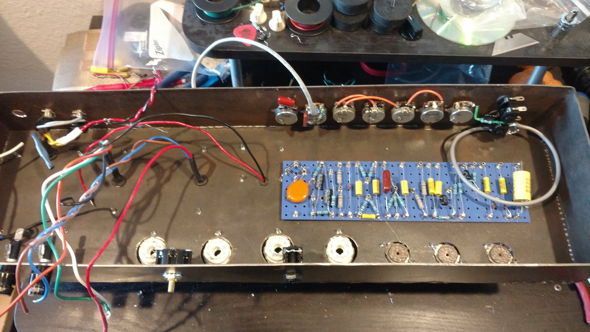
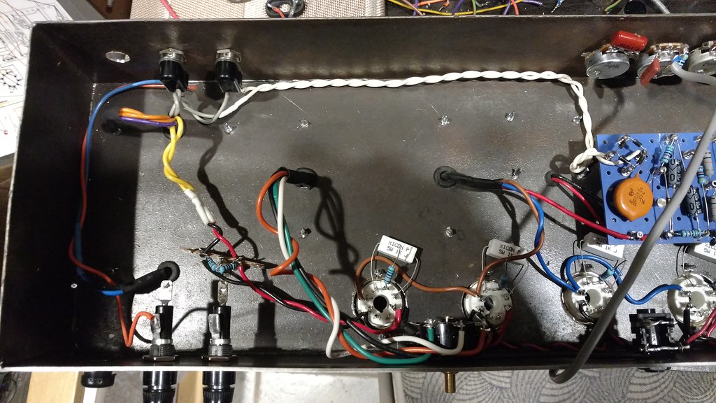
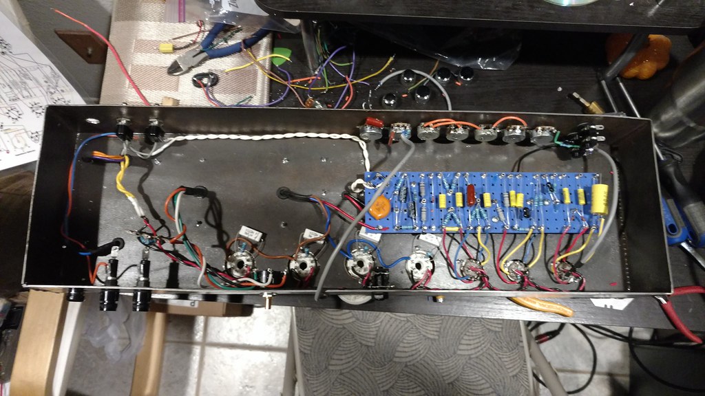
Well, went for position 1.5. Ha!
 Jcm800 progress
 by
Paul Abbott, on Flickr
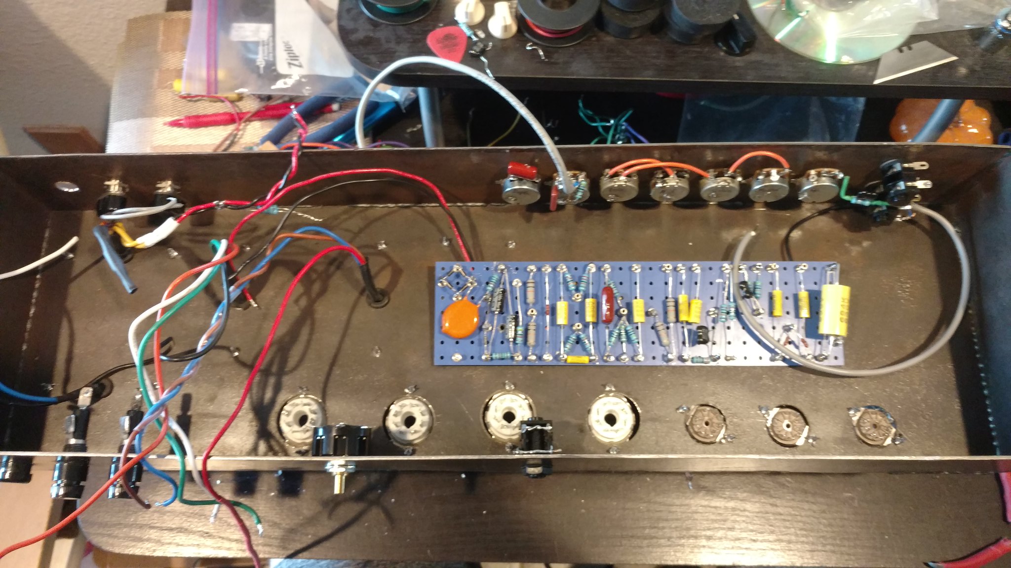
 Jcm800 progress
 by
Paul Abbott, on Flickr
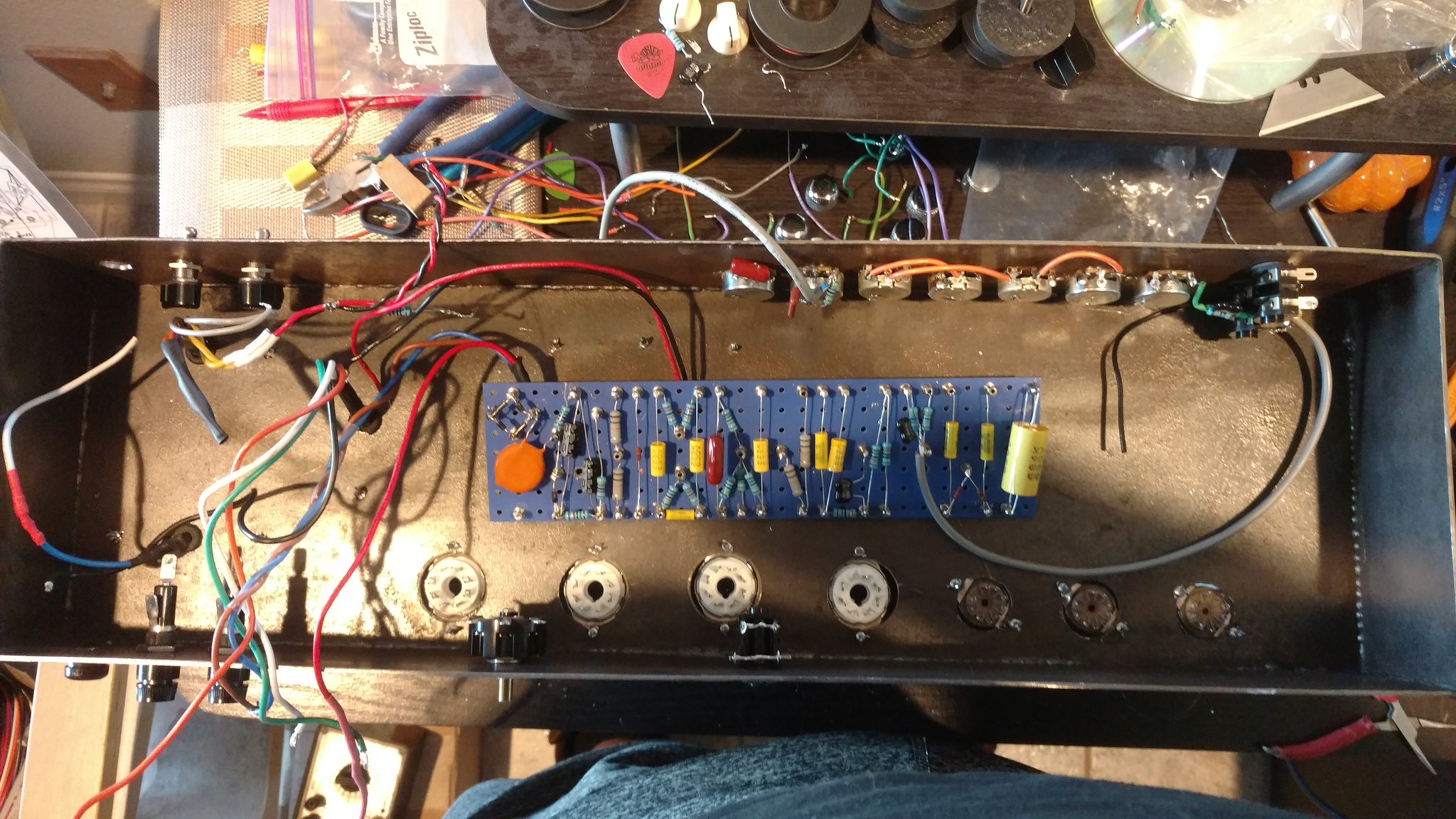
 Jcm800 progress
 by
Paul Abbott, on Flickr
Obviously am not done yet. I have managed to use a tag board to clean up the artificial center tap for the heaters. Its all the way to the left of the chassis.
I do have a long run of HT coming from the transformer/standby switch to the rectifier. I have twisted those wires (white) and stuffed them into the corner of the chassis then right angled it up to the board. Hoping this doesn't cause too much noise as it is AC to the board. If it is troublesome, then I will rectify it down near the transformer and do a long run of DC to the board.

-
neikeel
- Senior Member
- Posts: 7231
- Joined: Tue Dec 06, 2005 8:31 am
- Location: Suffolk, England
Post
by neikeel » Mon Oct 09, 2017 1:56 pm
You are learning lots as you go.
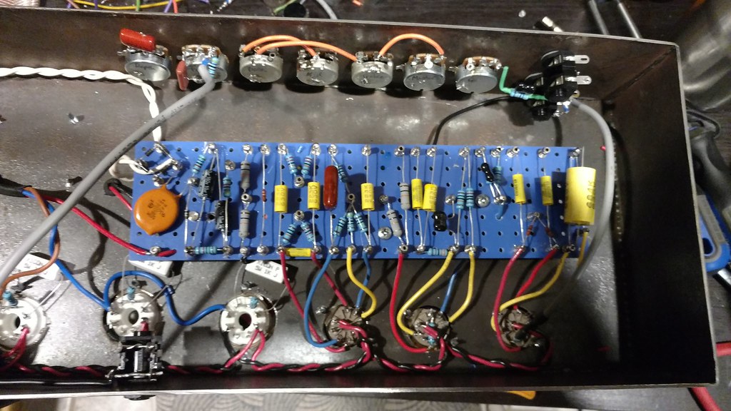
As a side issue I suggest you lift the sceen resistors up over the sockets (take a peek at some original Marshalls - or even better George's plexi replicas.
Try and use those as a guide to your wiring runs etc.
Neil
-
marshallnoise
- Senior Member
- Posts: 169
- Joined: Wed Jun 10, 2015 1:58 pm
- Just the numbers in order: 13492
- Location: Oceanslime, CA
Post
by marshallnoise » Mon Oct 09, 2017 3:35 pm
neikeel wrote: ↑Mon Oct 09, 2017 1:56 pm
You are learning lots as you go.
As a side issue I suggest you lift the sceen resistors up over the sockets (take a peek at some original Marshalls - or even better George's plexi replicas.
Try and use those as a guide to your wiring runs etc.
Indeed I am. Execution is the biggest thing. I know I am capable of doing nice looking work, but I always wonder why. Moot point here because nice looking work is necessary.
So is the reason for lifting the screen resistors 1K5W in the air because they get hot? Just curious.
EDIT: If you are talking about the 5.6K grid stoppers, those are pointed straight up. I did leave the screen grid resistors on the chassis.
-
neikeel
- Senior Member
- Posts: 7231
- Joined: Tue Dec 06, 2005 8:31 am
- Location: Suffolk, England
Post
by neikeel » Mon Oct 09, 2017 6:37 pm
marshallnoise wrote: ↑Mon Oct 09, 2017 3:35 pm
So is the reason for lifting the screen resistors 1K5W in the air because they get hot? Just curious.
Yes they do and can desolder themselves if catastrophic tube failure so a wrap around the turret is a good idea.
Neil
-
marshallnoise
- Senior Member
- Posts: 169
- Joined: Wed Jun 10, 2015 1:58 pm
- Just the numbers in order: 13492
- Location: Oceanslime, CA
Post
by marshallnoise » Mon Oct 09, 2017 7:14 pm
neikeel wrote: ↑Mon Oct 09, 2017 6:37 pm
marshallnoise wrote: ↑Mon Oct 09, 2017 3:35 pm
So is the reason for lifting the screen resistors 1K5W in the air because they get hot? Just curious.
Yes they do and can desolder themselves if catastrophic tube failure so a wrap around the turret is a good idea.
Roger that.
-
Littlewyan
- Senior Member
- Posts: 200
- Joined: Fri Dec 06, 2013 9:27 am
- Just the numbers in order: 13492
- Location: United Kingdom
Post
by Littlewyan » Wed Oct 11, 2017 8:22 am
Sorry for my absence. Been a bit busy! Looking good so far man!
-
marshallnoise
- Senior Member
- Posts: 169
- Joined: Wed Jun 10, 2015 1:58 pm
- Just the numbers in order: 13492
- Location: Oceanslime, CA
Post
by marshallnoise » Sat Oct 14, 2017 11:38 pm
Ok, the whole amp is wired up. But, I am getting 470vdc in the preamp where it should be half of that. All my dropping resistors check out fine as far as values. VDC at the rectifier is 540 and at the power tubes it's 500.
Mind you, I am testing these voltages with no tubes.
Any ideas?
-
neikeel
- Senior Member
- Posts: 7231
- Joined: Tue Dec 06, 2005 8:31 am
- Location: Suffolk, England
Post
by neikeel » Sun Oct 15, 2017 1:28 pm
Drop in some tubes and they will drop by about 10%
Neil
-
marshallnoise
- Senior Member
- Posts: 169
- Joined: Wed Jun 10, 2015 1:58 pm
- Just the numbers in order: 13492
- Location: Oceanslime, CA
Post
by marshallnoise » Sun Oct 15, 2017 1:34 pm
neikeel wrote: ↑Sun Oct 15, 2017 1:28 pm
Drop in some tubes and they will drop by about 10%
Roger that.
-
marshallnoise
- Senior Member
- Posts: 169
- Joined: Wed Jun 10, 2015 1:58 pm
- Just the numbers in order: 13492
- Location: Oceanslime, CA
Post
by marshallnoise » Tue Oct 17, 2017 12:31 am
Alright. I popped in the tubes and still had voltage problems. Then I traced the circuit against the layout and realized, like a dumbass, that I didn't have grounds hooked up for most of the preamp. That's the problem with walking away from a project and then picking it back up.
But, back to the heater supply problem, I now have an imbalanced heater voltage coming out of the transformer. I have 2.7 going to one side and 3.8 going to the other. I inadvertently swapped the hot and neutral wires on the power transformer primaries and I think I damaged the filament winding.
I have a 100 watt OR that came out of a Marshall 9200 (edit, I have no idea what this transformer is now that I researched it) power amp that I am considering putting in this amp for two reasons. One, in case I did damage the Bugera PT. And two, the BY voltage should be considerably less than the 535 i am getting out of the Bugera PT.
Thoughts? Comments?
-
neikeel
- Senior Member
- Posts: 7231
- Joined: Tue Dec 06, 2005 8:31 am
- Location: Suffolk, England
Post
by neikeel » Tue Oct 17, 2017 2:54 am
Isolate your 'damaged' PT secondaries and measure the ac with no load and post results
Neil