Soldano Hot Mod
Posted: Wed Dec 13, 2006 1:26 am
Can anyone explain a few things about this to me?
http://www.schematicheaven.com/newamps/ ... ot-mod.pdf
What is the symbol that is a straight bar like at the end of the 330k resistor? Is that ground?
Correct me if I am wrong, but looking at this schematic I would wire the 6k11 like this?
pin 1 on the tube to pin 9 on the 9 pin socket
pin 2 and 11 are tied together with a 200k resistor
pin 2 is tied to pin 6 on the socket, pin 5 to pin 6 on the socket via 2nf/1kv cap.
pin 3 to pin 8 on the socket
pin 4 to 2k7 resistor to (?)
pin 6 to pin 3 on the socket
pin 7 to pin 2 on the socket
pin 8 not used
pin 9 > 330k resistor wired in series to a 10nf/400V cap to pin 1 on the socket, this is junctioned with a 330k to (?) and at the pin 5 to pin 6 connection.
pin 10 & 11 on the tube are tied together
pin 12 to pin 4 on the socket, pins 4 & 5 on the socket are tied together.
Pins 1 & 12 on the tube are internally tied together?
Ok now here is the question.... Where would one find a housing to encapsulate this componants while having a male 9 pin socket and a female 12 pin socket? I guess an easy way would be to create my own box, but would this be feasible?
Something like this perhaps? http://www.apexelectronic.com/connectors.htm scroll down to the 9 pin tube style Connector and modify it to accept the componants as well as another type of adapter to seat the 12 pin socket to?
Actually the picture of one of these looks cheapo
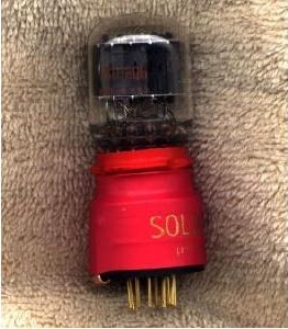
The tube is shrink wrapped to the 9 pin socket, this is evan easier now come to think about it.
http://www.schematicheaven.com/newamps/ ... ot-mod.pdf
What is the symbol that is a straight bar like at the end of the 330k resistor? Is that ground?
Correct me if I am wrong, but looking at this schematic I would wire the 6k11 like this?
pin 1 on the tube to pin 9 on the 9 pin socket
pin 2 and 11 are tied together with a 200k resistor
pin 2 is tied to pin 6 on the socket, pin 5 to pin 6 on the socket via 2nf/1kv cap.
pin 3 to pin 8 on the socket
pin 4 to 2k7 resistor to (?)
pin 6 to pin 3 on the socket
pin 7 to pin 2 on the socket
pin 8 not used
pin 9 > 330k resistor wired in series to a 10nf/400V cap to pin 1 on the socket, this is junctioned with a 330k to (?) and at the pin 5 to pin 6 connection.
pin 10 & 11 on the tube are tied together
pin 12 to pin 4 on the socket, pins 4 & 5 on the socket are tied together.
Pins 1 & 12 on the tube are internally tied together?
Ok now here is the question.... Where would one find a housing to encapsulate this componants while having a male 9 pin socket and a female 12 pin socket? I guess an easy way would be to create my own box, but would this be feasible?
Something like this perhaps? http://www.apexelectronic.com/connectors.htm scroll down to the 9 pin tube style Connector and modify it to accept the componants as well as another type of adapter to seat the 12 pin socket to?
Actually the picture of one of these looks cheapo
The tube is shrink wrapped to the 9 pin socket, this is evan easier now come to think about it.