This is not my 1st build
I followed start up procedures.
120ac
Pwr on
approx. 325 VDC with GZ34 at standby.
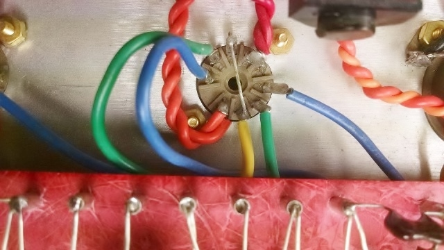
-40 at pin 5 V4 and V5, bias full CW
V1 and V2 voltages are within spec.
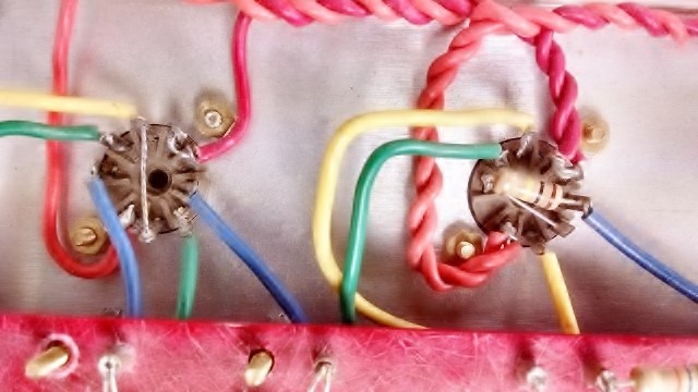
V3 I have concern for Plate and Anode voltages
V3
pin 1 271VDC
pin 3 & 8 155VDC
pin 6 266VDC
Cathodes are way out from Spec of 48VDC
(and yes there's a 470 resistor in R18)
With the kt66s installed and warmed up I took it out of standby.
and my current limiter starts to glow!!??
with the exception of V3 concerns, (stated earlier)
all is fine till I apply HT
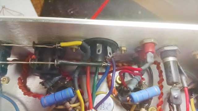
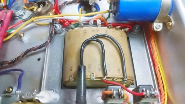
Marstran PT is 1202-55
OT is 1324/103
OT primary
V5 Blk start
Brn to cap choke
V4 Red finish
Secondary
16 Blue
8 Green
4 Orn
common Yel
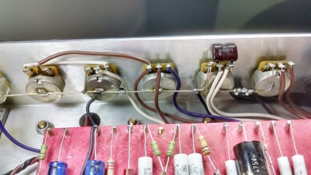
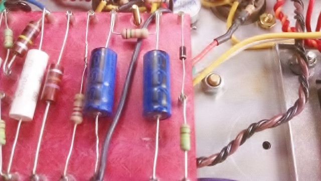
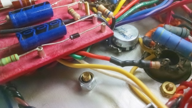
Parts all in spec
I've been over and over the schematic
and everything is in its place and the right value.
1st attempt to test and power up was back in March 14".
Followed procedures, got to the put in the pwr tubes and
switched on HT part and it made little noise and unable to
turn up volume. I went thru schematic and board couldn't
find anything out of place or of wrong value.I went thru start
up again blew the mains fuse.
(I now use a 200Watt lamp in series
for limiting and safety. Works great!)
I set it aside till this week.
I started again with start up, (this time using the 200 watt
series current limiter). All was fine till HT was applied with the kt66 in sockets.
The current limiter starts to glow!
Something is causing it to draw current with the Power tubes in and the HT on and I don't know what/why?
HHHHHHHHHHHHEEEEEEEEEEEEEEEEELLLLLLLLLLLLLLPPPPPPPPPPPPPPPPP!!!!!!?????
Please, I'm going nuts on this one.
Thank you in advance I appreciate
any help
I'll take responses at madnis45@cox.net