OK, I'm done!!!!

I put in a few more hours Saturday night, until I just couldn't do any more... Then I picked it up Sunday afternoon, and finished up.
More pics...
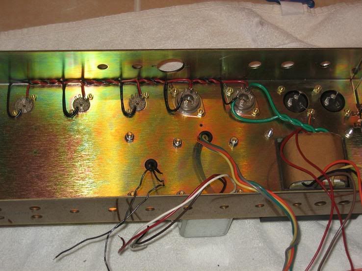
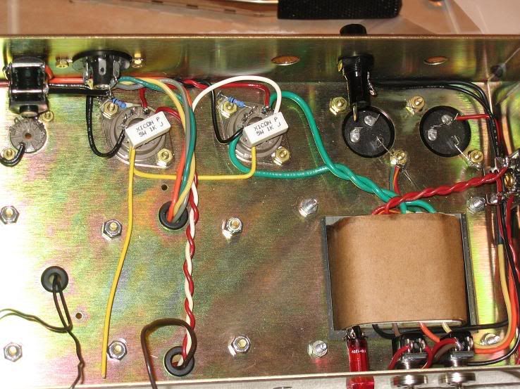
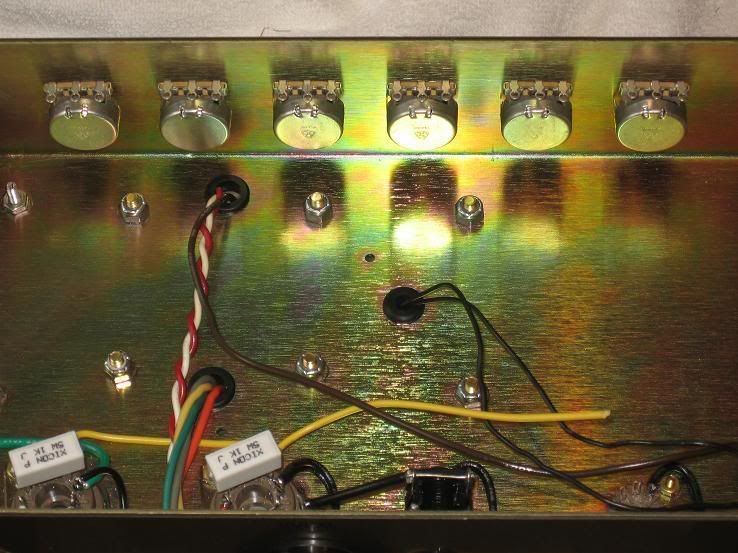
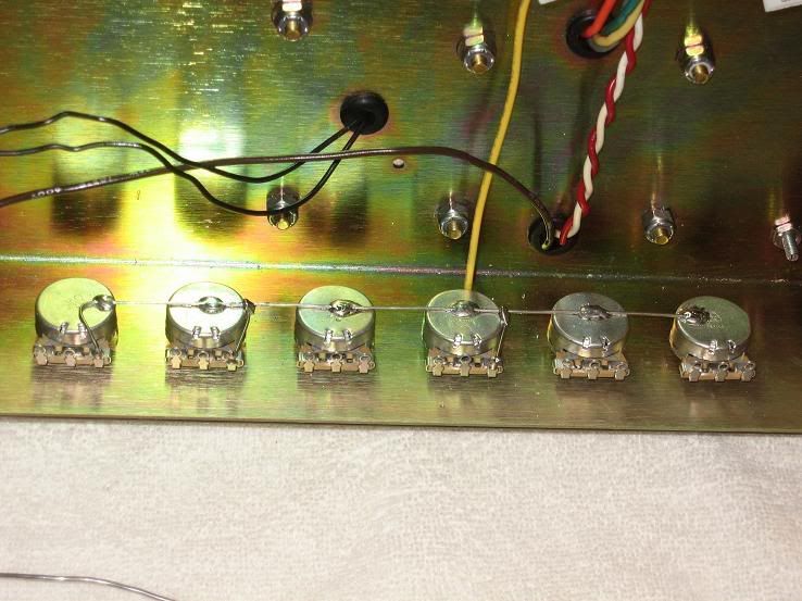
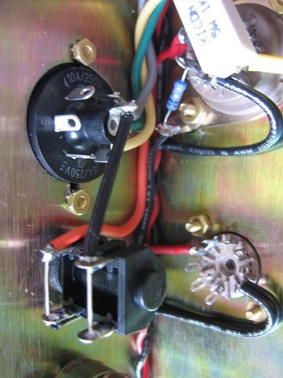
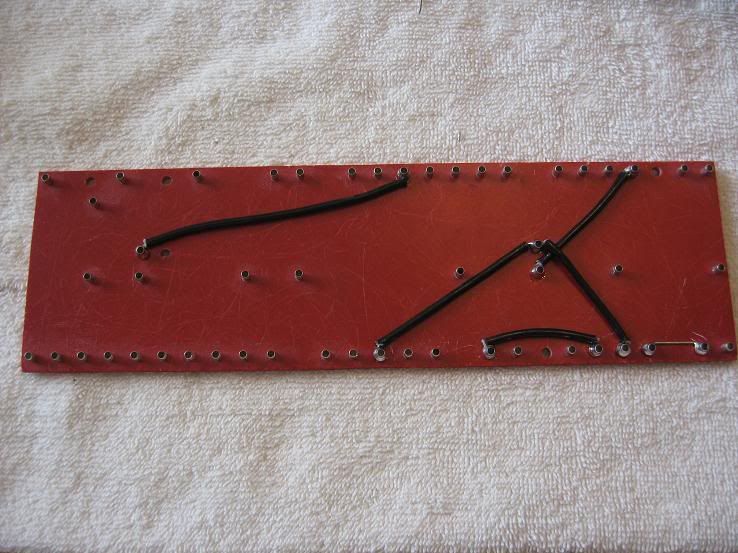
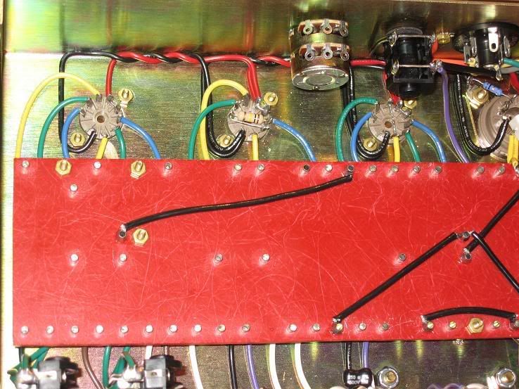
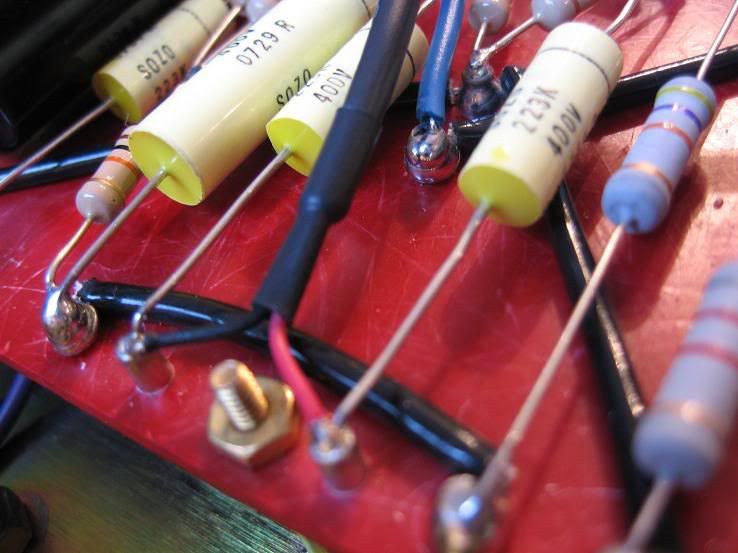
Working on the pot wires from the bottom of the board:
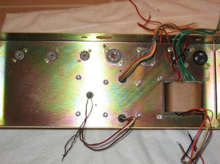
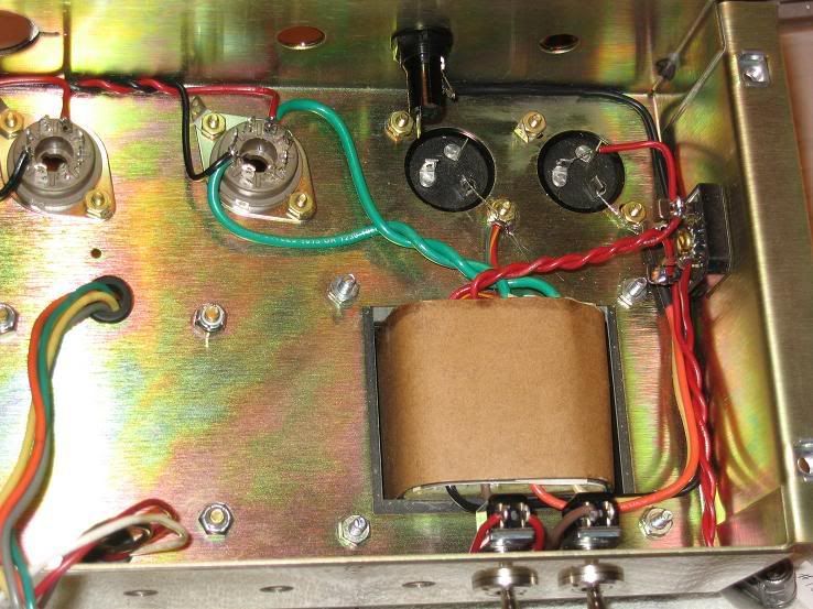
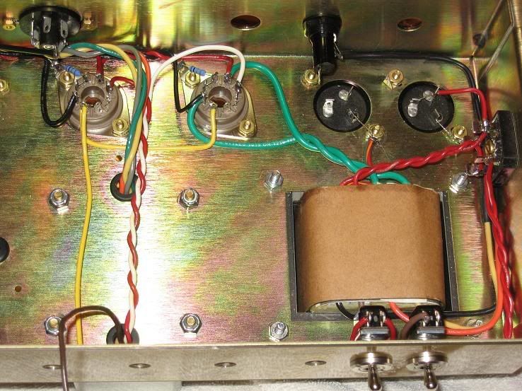
Preamp tubes wired up:
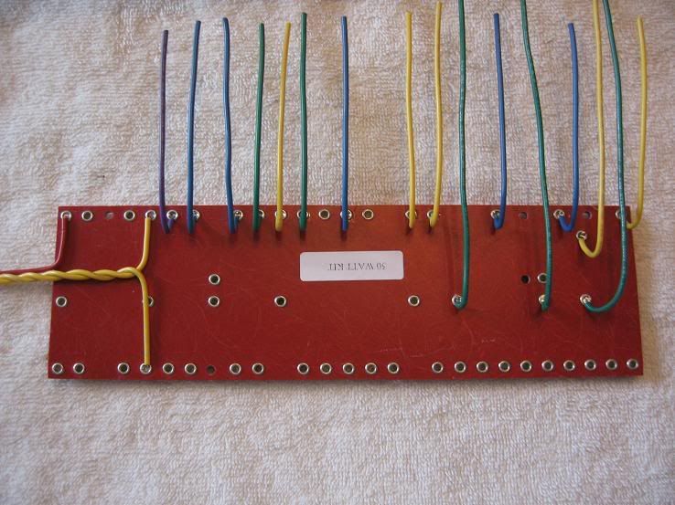
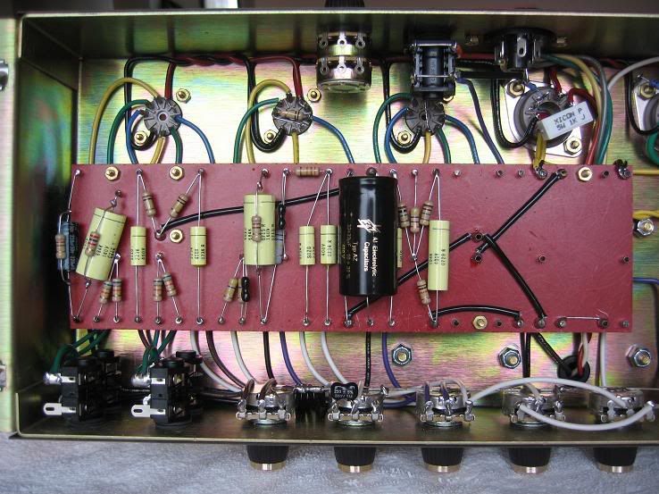
Board patially populated:
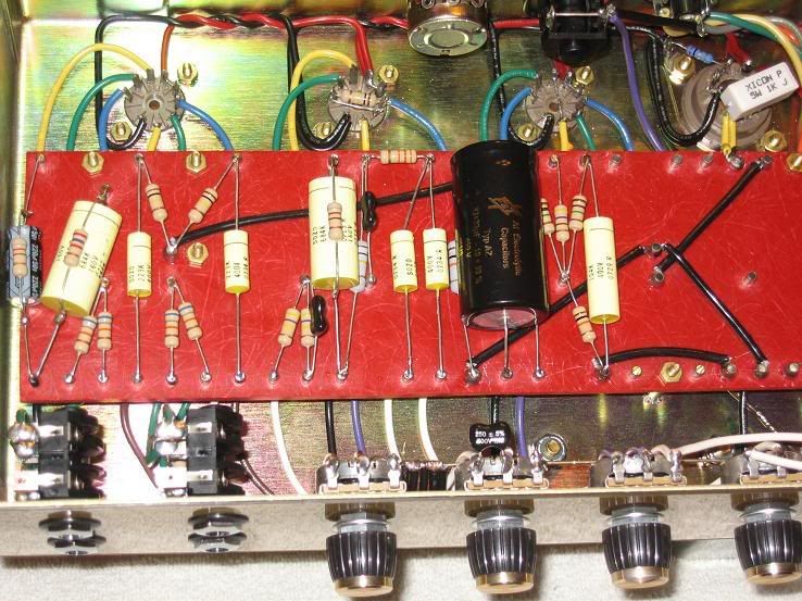
That's where I ran out of steam Saturday night, and went to bed. It was like 2:00am and I was exhausted.
Sunday morning I spent hanging out with the family, and then started up again after lunch.
Ok, here we go, the home stretch!
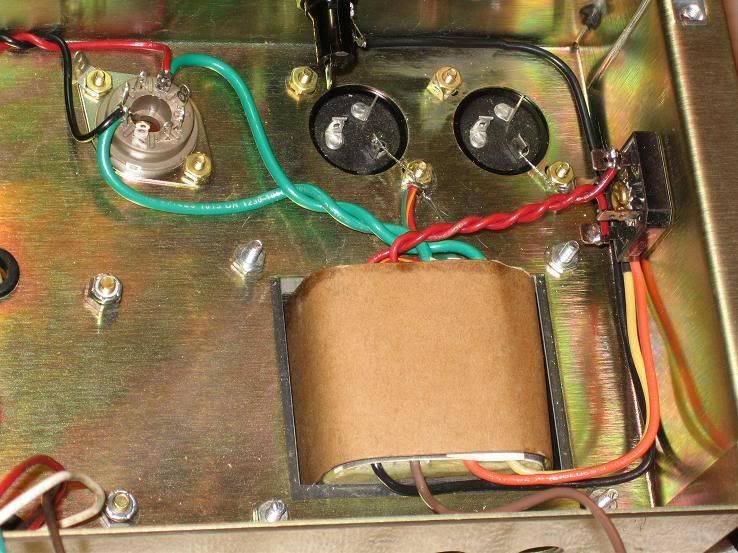
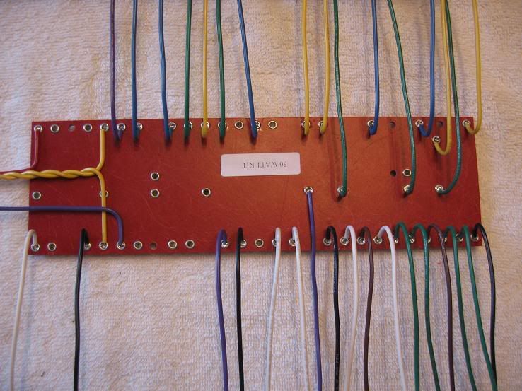
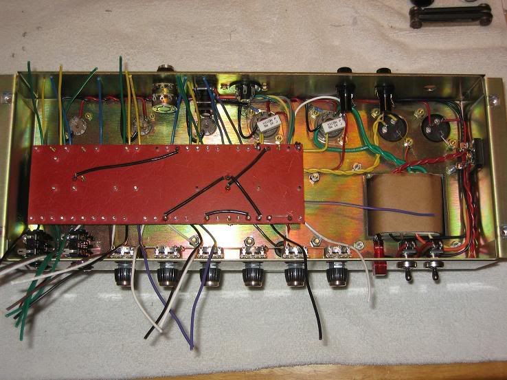
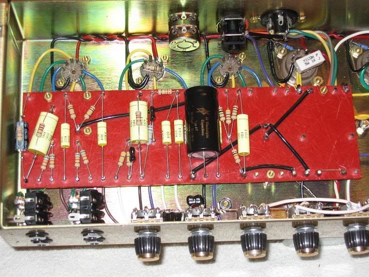
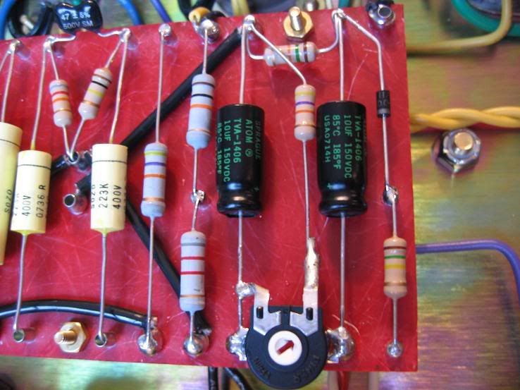
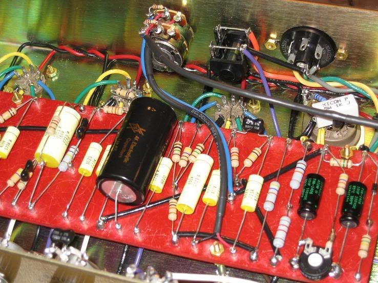
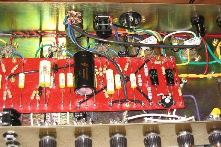
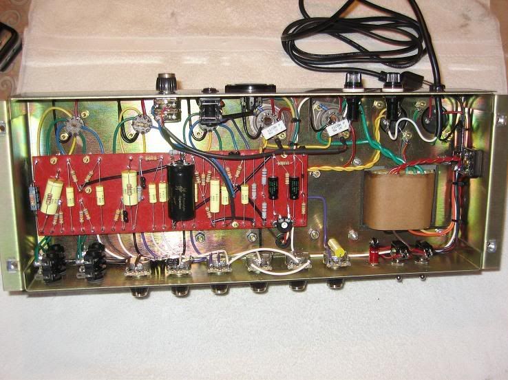
Finished populating the board:
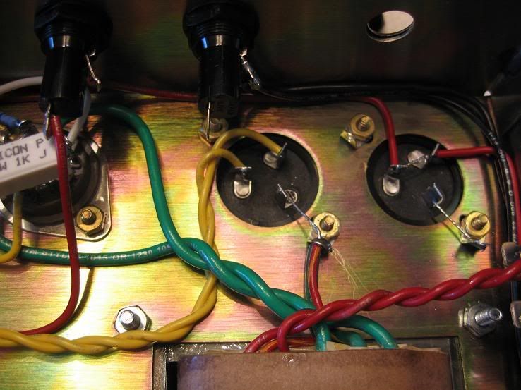
Bias circuit with bias adjustment pot mounted on the board (Yes, I took care of that unsoldered turret between the 2 .022uf Sozos

):
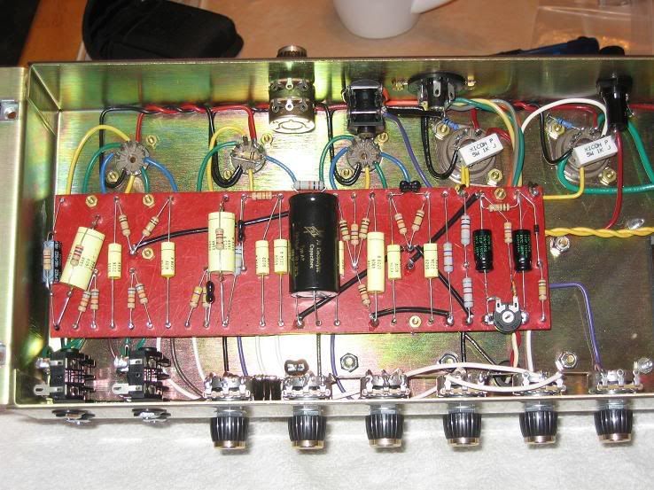
Power cable and PPIMV installed... HEY! I THINK I'M DONE!!!!!
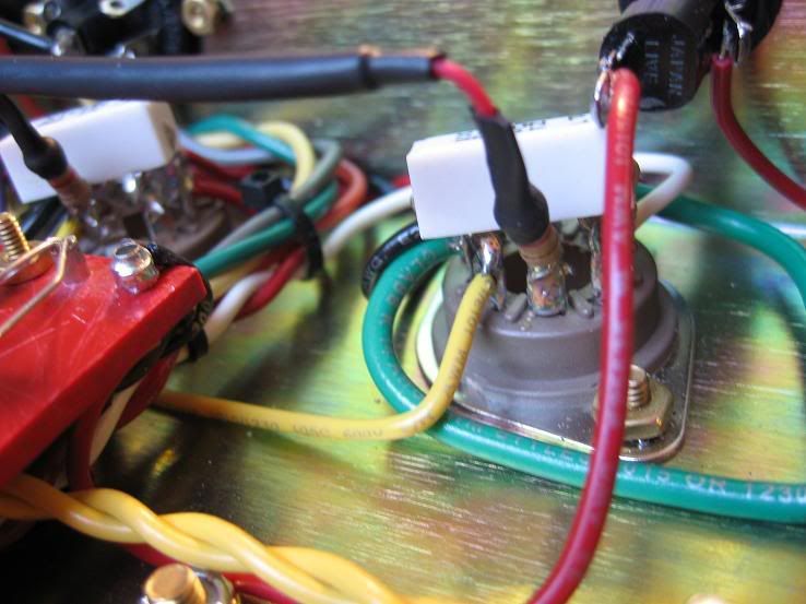
PPIMV dual 250K pot:
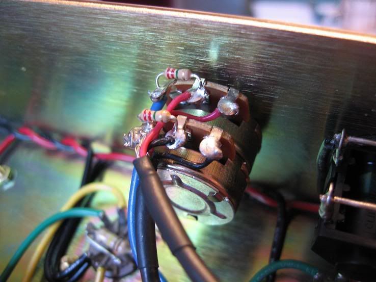
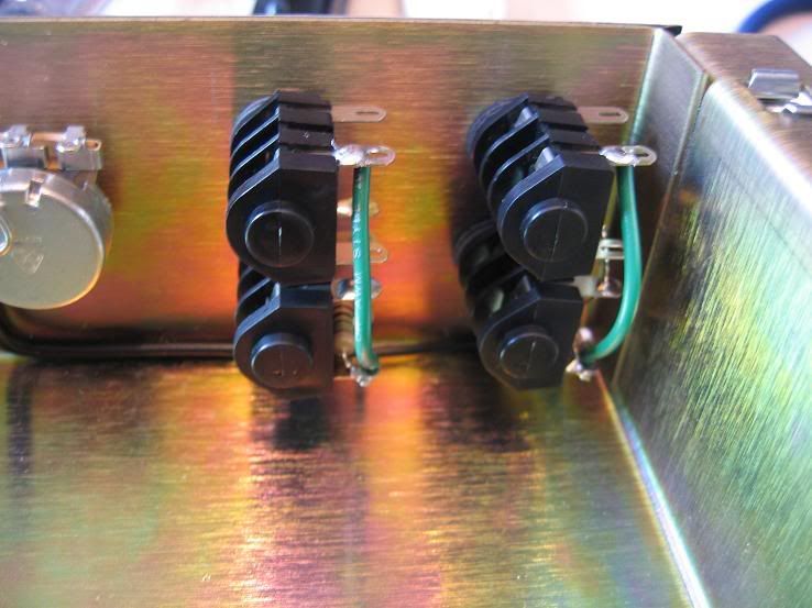
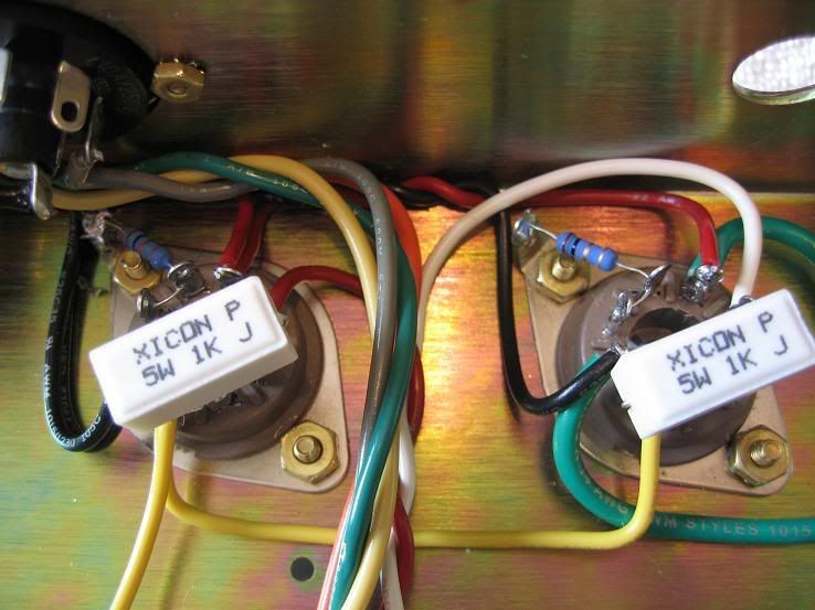
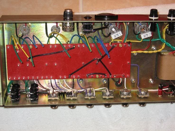
Close-up of PPIMV shielded wiring connected to the board:
PPIMV wiring:
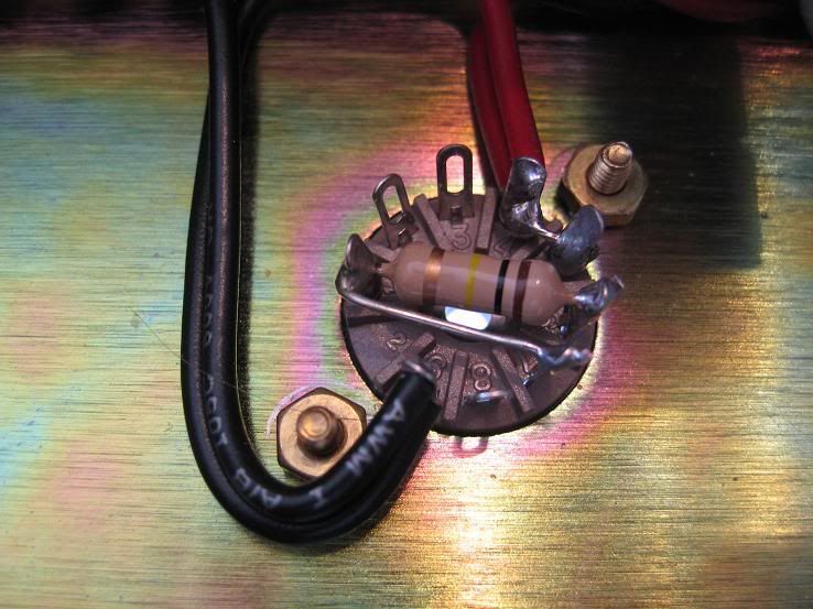
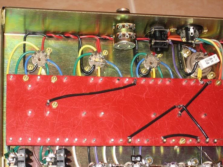
V5 grid stopper resistor on pin 5, connected to PPIMV shielded wire:
V4 grid stopper resistor on pin 5, connected to PPIMV shielded wire:
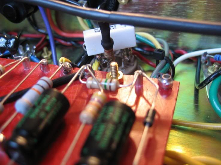
One last PPIMV shot:
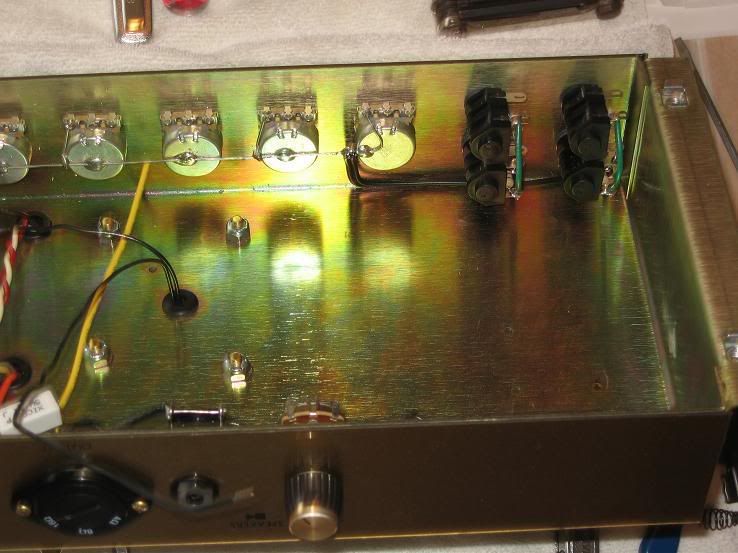
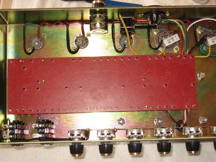
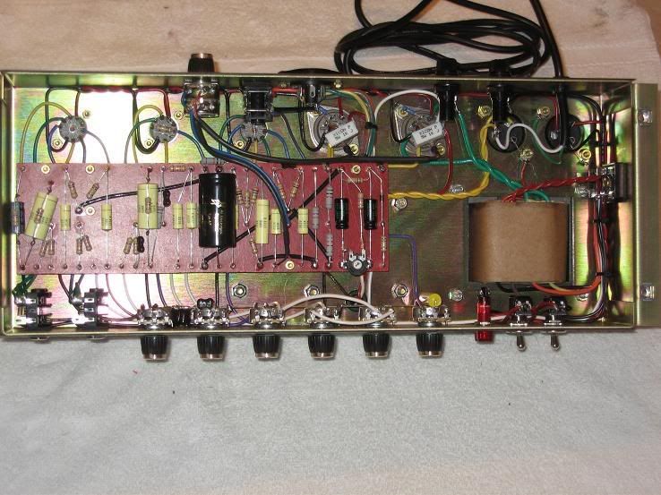
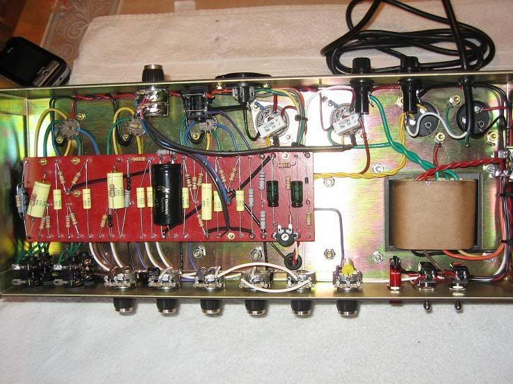
Full chassis shot:
Another full chassis shot:
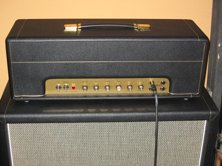
Rear:
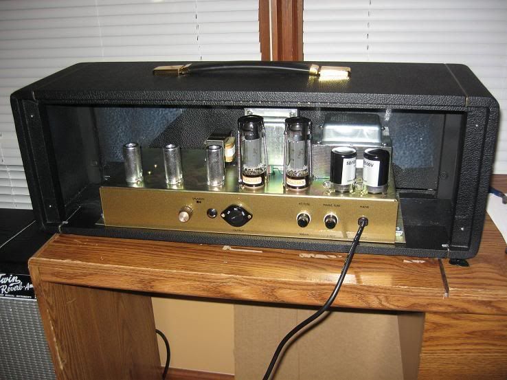
Tubes:
I have Mullard reissue EL34's for power, and the pre's are a NOS Mullard in V1, a NOS Amperex Bugle Boy in V2, and an old Silvertone in V3 (which I think is also an Amperex, it says made in Holland)
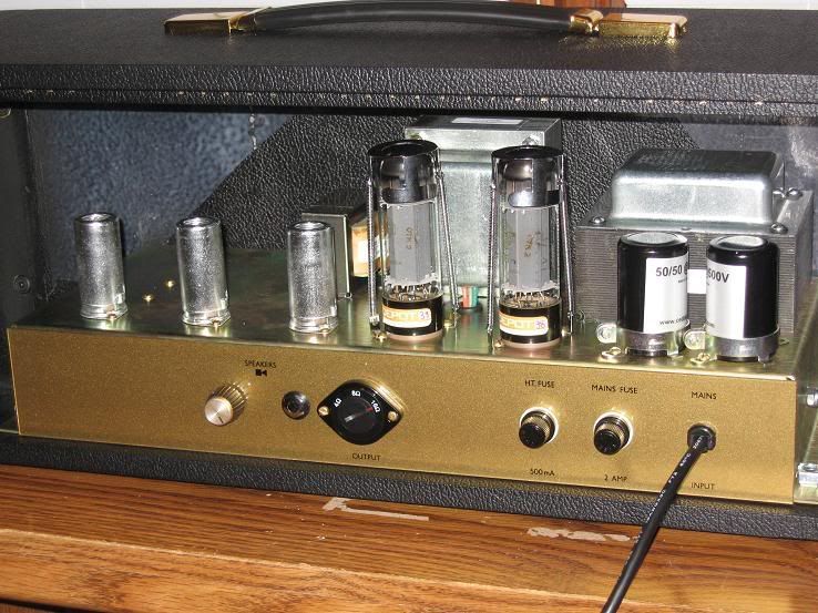
Head:
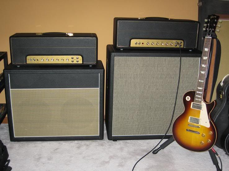
Group shot with its little brother (JTM 45) on the left and my Les Paul:
Testing went very smoothly, all my voltages were right where they should be. I had one head scratching moment on page 26 (Testing Part 1) where it said I should have about 450V DC on the positive terminal of the bridge rectifier, but I was only reading 315V DC. The directions should have said to turn the standby switch on and THEN take that measurement. Once I did that I got 470V DC.
Everything else was right in range, so I installed my tubes and continued on. Installed the pre's first and took measurements, then installed the output tubes, hooked up a speaker cab and measured again. All looking good, and normal light hiss from the speakers when turning up either volume pot.
Then I set the bias. My B+ voltage is 449V, so I biased the amp at 39mA (70% plate dissipation). My tubes are pretty closely matched, only off by about 2mA.
So now it was time to fire it up and plug in the Les Paul!!! I have to say that I IMMEDIATELY fell in love with the tone of this amp. The clarity, the punch, the sustain, the harmonics, the controlled feedback, I am in tone heaven!! I get a nice crunch and singing sustain starting between 6 and 7 on volume 1, and its sweet spot seems to be about 7.5 - 8.
I built a JTM 45 kit a few months ago, and I have grown to love that amp. But the point is, I
had to grow to love it over the course of a couple of months, making modifications, finding ways to tame the fizz, etc.
This 50W kit just floored me right out of the gate. I'm getting sounds I have been wishing I could get from the JTM, but the JTM is just a different animal. It definitely has its place though, especially for playing bluesy stuff. The 50W is a ROCK amp.
With the Les Paul, I'm getting Cream, Free, Allmans, Zeppelin, all the classic plexi tones. I plugged in the Strat, and while I still have some tweaking to do, I was definitely getting into Hendrix territory.
The only thing I'm considering changing so far on the 50W is the value of the bright cap on the channel 1 volume pot. I've got a 250pf there right now and it has a slight case of ice pick-y-ness at lower volumes (stock value is 500pf, I think that would make my ears bleed

). I think I'll try a 100pf there, that's what I have in the JTM.
Hope you all enjoyed my build, I know I did! (I am enjoying playing it too!!!!!!)
George, this kit is a HOME RUN.