New JTM/JMP50 build w/switchable rectifier

Get support and show off your MetroAmp 50 Watt kit builds.

Moderator: VelvetGeorge

shakti
Senior Member
Posts: 2053
Joined: Tue Apr 05, 2005 9:06 am
Just the numbers in order: 7
Location: Ramnes, Norway

New JTM/JMP50 build w/switchable rectifier

Post by shakti » Tue Apr 10, 2012 2:06 am

Posting this here in the 50W section as well as in the DIY section.

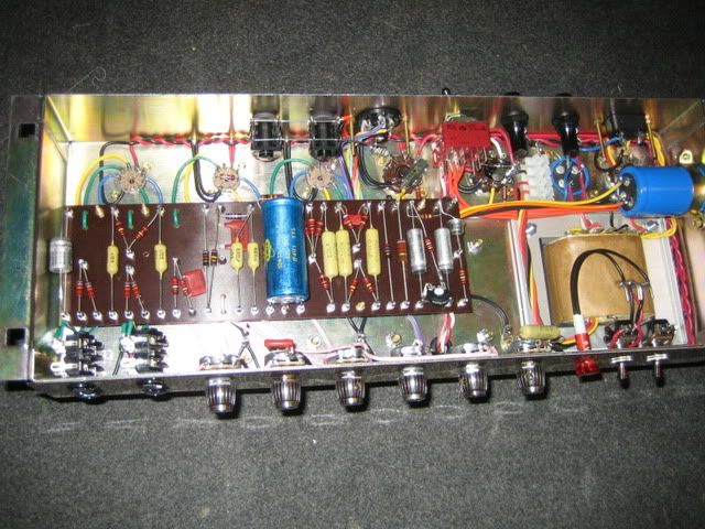
I finished this thing over the holiday:
Image

It's a bit of a hybrid spec 50-watter. Built with Marstran chassis and 1202-118 PT, M e r r e n 78-139 OT, Metroamp 352-114 choke, Sparky JTM black flag faceplate, Brian H board and Piher resistors like an early/mid-67 tube rectified black flag JTM50, i.e. Mustards, Lemcos and NOS Erie preamp filter cap, the other filter caps are F&T. Single 8.2k voltage dropper between screens and PI, 270k mixer resistors. Currently have negative feedback as 27k@8ohm, but might go with 16 ohm. I am still waiting for the rear faceplate, so will tidy up the rear panel connections when that arrives.

There are a few very rare amps with black flag faceplate but stock diode rectification, just as there are some JMP faceplate ones with tube rectifier. Typically those transitional amps had the single voltage dropper, 470k mix resistors and only 32uF mains, 32uF screens and 16uF PI filtering. Since I like the '68 spec JMP50s so much, I decided to make this amp switchable with some "in-between" values. Visually/aesthetically it's more of an early black flag style amp. In tube mode I have 32uF mains, 32uF screens, 32uF PI and 32+32uF preamp filtering. In diode mode I add another 32uF to the mains filtering for a total of 64uf. Late '67/early 68 ones sometimes had 48 or 50uF, later '68 ones crept up to 80uF or even 100uF. I chose 64uF since that was the easiest (dual 32) plus I wanted it to stick out from the tube mode a little more.

It sounds really nice and is very quiet, but does exhibit some "new amp stiffness" still, as I only have about 2-3 hours on it yet. We'll see how it fares with more burn-in, but I can't shake the feeling that those F&T caps just don't sound right in Marshall circuits. Anyone with me? I feel they're a bit grainy and stiff, not the right roundness to the tone. I just don't know which alternative might work better...

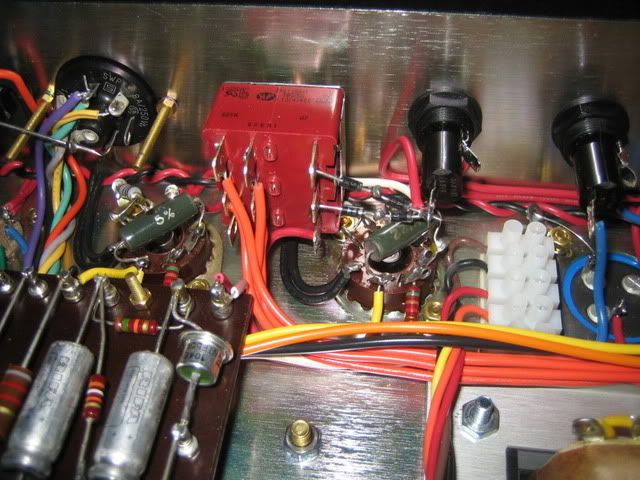
Anyway, here's a shot of how I wired the tube/diode switch. I used the 3PDT on/off/on switch that was used in the Metro dual voltage 12-series amps and is sold by Valvestorm. Two poles are used to switch the AC secondaries on the PT to either tube or diode rectifier. The third pole is used to switch in an extra 32uF in diode mode to the junction turret at the end of the board, where B+ comes from the standby switch via 32uF to meet with the OT CT and one choke wire.
Image

And now for the question: I hadn't counted on needing to adjust the bias for tube/SS mode individually. I thought the difference would be minor enough that it didn't matter (for the record, I get 420V with diodes and 410V with tube rectifier). However, my reflected bias reading (via the 1 ohm resistors) drops quite a lot in tube mode. If I have it at 45mA in diode mode (xf2 Mullards), it drops to 35mA in tube mode. Along with the lower plate voltage, it makes for a fairly cold bias in tube mode, and it sounds noticeably thinner. So I figure I need to put in some adjustment in tube mode. As I understand it, I should add some resistance to the raw bias feed (actually one half of the AC secondaries) in tube mode, is that correct?
Now the way I see I can do it on this switch, is to move the bias feed to the diode side of the switch, then put a resistor jumper between the center pole and the diode side. So when the switch is in diode mode, the bias circuit gets the full voltage. And in tube mode, the bias circuit draws through the resistor. Will that work?

The only problem I see is this: as the switch is now wired, it works like an alternate standby switch. I can switch from tube to diode mode without any problems, as the middle position is an "off" position where the AC secondaries get cut off from the rectifiers. I like this, as it means the tube rectifier only gets hit with HV AC when it's actually in use. The tubes remain biased regardless of the switch setting, as the bias feed is independent of the switch. However, if I were to wire it like I suggested above, the tubes would not be biased when the switch is in the middle position...or will they? I suppose they will still draw bias current via the resistor jumper...I'm getting confused. I want to avoid the problem that Marshall had in the early 70s, where the bias feed was on the far end of the standby switch, which meant that when the standby switch was thrown, the tubes were hit with full B+ before the bias circuit had charged up = massive current draw and burnt out PTs. As I understand it, this is the reason you see so many early 70s 50-watters with replaced PTs.
Anyway, does anyone see any problems with wiring it like I suggested?
JTM45 RS OT, 1973 18W, JTM45/100, JTM50, JMP50 1986, JMP100 "West Coast", AC15, AC30, BF Super Reverb, Boogie Mk 1, Hiwatt CP103, DR103

shakti
Senior Member
Posts: 2053
Joined: Tue Apr 05, 2005 9:06 am
Just the numbers in order: 7
Location: Ramnes, Norway

Re: New JTM/JMP50 build w/switchable rectifier

Post by shakti » Tue Apr 10, 2012 3:50 pm

No 50W love around here? Do I have to post this in the Van Halen section to get any action...? :lol:
JTM45 RS OT, 1973 18W, JTM45/100, JTM50, JMP50 1986, JMP100 "West Coast", AC15, AC30, BF Super Reverb, Boogie Mk 1, Hiwatt CP103, DR103

shakti
Senior Member
Posts: 2053
Joined: Tue Apr 05, 2005 9:06 am
Just the numbers in order: 7
Location: Ramnes, Norway

Re: New JTM/JMP50 build w/switchable rectifier

Post by shakti » Wed Apr 11, 2012 3:08 am

Let's try to kick-start this topic, shall we?

It's sounding a little harsh still, but again it needs burn-in. However, it appears to be a slightly different sort of harsh than I've experienced in other builds. It's somewhat buzzy, static-y, like a midrange and high-end "clutter". And I notice it much more in solid state mode than tube mode...so I am looking at the rectifier diodes.

This is a subject which I've sort of ignored yet. I put some FREDs in a '71 JMP50 many, many years ago and liked the change, but to be honest it wasn't an apples and apples comparison, as I had a tech do it and changed the tubes at the same time. In my previous JMP50 build (more or less stock Metro kit, but with M e r r r e n OT and premium Sozos, built back in 2008) I used a bridge retifier, and I don't recall this sort of noise in that amp, even before burn-in. In my other builds I've used the top hat diodes for looks. In my 12-series I had some beefier ones, but in my black flag JTM100 build and this one, I've got those tiny little 1A ones, and I *think* they are 1N4007s.

Been reading up on this a little bit, and I am beginning to suspect this may be part of the problem. Apparently the 1N4007s are slower in response, and can induce a "ringing" sort of noise in the amp. Some people say the actual placement of the diodes can also have an effect. In this case I have them mounted on the switch, as you can see, but fairly close to the output tubes and not very far from the preamp tubes. In any case, I am going to try either the beefier ones I have (which I believe are 3A, but I' not sure if they are a UF or 1N type, will have to check). Even more interestingly, I might try to swap the diodes in my JTM100...there's 16 of them per rectifier! But I assume any noise it induces will be regardless (or maybe even proportional??) to the number of diodes, and not less because of more diodes?

Any opinions on diode selection? Is there an advantage to swapping the bias diode as well? And how do the top hat style diodes fare in comparison to the UF types?
JTM45 RS OT, 1973 18W, JTM45/100, JTM50, JMP50 1986, JMP100 "West Coast", AC15, AC30, BF Super Reverb, Boogie Mk 1, Hiwatt CP103, DR103

shakti
Senior Member
Posts: 2053
Joined: Tue Apr 05, 2005 9:06 am
Just the numbers in order: 7
Location: Ramnes, Norway

Re: New JTM/JMP50 build w/switchable rectifier

Post by shakti » Wed Apr 11, 2012 4:01 am

Found this thread with some fantastic clips of different types of diodes in both the rectifier and the bias circuit...what a terrific resource!!

http://forum.metroamp.com/viewtopic.php?f=4&t=14392" onclick="window.open(this.href);return false;

Methinks I'll be doing some diode swapping...
JTM45 RS OT, 1973 18W, JTM45/100, JTM50, JMP50 1986, JMP100 "West Coast", AC15, AC30, BF Super Reverb, Boogie Mk 1, Hiwatt CP103, DR103

User avatar
neikeel
Senior Member
Posts: 7231
Joined: Tue Dec 06, 2005 8:31 am
Location: Suffolk, England

Re: New JTM/JMP50 build w/switchable rectifier

Post by neikeel » Wed Apr 11, 2012 4:52 am

No that there is no love Thorlief.......the amp looks fantastic, it is just that I have been thinking of a simple and easy way to solve the switching issue, as you know I wanted to do the same, but installing a dual standby switch on the front in the normal place. After all Dennis Cornell has a 45/50 amp with dual switching!

My thought were:

If you have the bias fed from the hot side of the switch direct from the PT the PT should be ok with that, the problem is when you switch that hot side to either of your rectifier options.........you are getting different B+ and therefore bias on the output valves.
The way to correct for your differential bias would be to use the spare limb of your switch (only using two parallel connections at the moment for each half of the PT, one with bias feed) would be to use the spare switch to flick a second bias resistor in parrallel with the one you have to lower or raise the value of the bias resistor in that particular mode (you could employ the resistor in either mode whether you wanted to go higher or lower. Even better use a resistor and pot like you can use on the daul voltage 12 series type amps. I did this once in a slightly different way with one of those amps.

As far as diodes I have used the UFs and they work well, not sure I can hear any difference. I just picked up some of these to try:
http://www.ebay.co.uk/itm/BY127-DIODE-1 ... ctrical_Co you get 10 in a pack (enough for a JTM45/100 and another amp!
Neil

shakti
Senior Member
Posts: 2053
Joined: Tue Apr 05, 2005 9:06 am
Just the numbers in order: 7
Location: Ramnes, Norway

Re: New JTM/JMP50 build w/switchable rectifier

Post by shakti » Wed Apr 11, 2012 5:35 am

Not sure if I follow your thinking about the bias adjustment quite as you intend...

I think of it in these terms: the switch has three poles, i.e. I can switch three "parameters". When I have it wired as I have, breaking the AC secondaries before they hit the rectifiers, two of the poles will be taken up to feed the two AC secondaries to either a tube or a diode rectifier. The last pole is used to switch in additional filtering to the output tube plates.

An alternate way to do it is to feed AC to the tube and diodes simultaneously, and then switch the resultant B+(tube) or B+(SS) to the middle lug (pole) of the switch. That leaves you with one pole to switch additional filtering and one pole to deal with the bias.

However, I chose the first method for a couple of reasons: It means the AC never hits the tube when it's not in use. It may not do so in the other mode of switching either, but it does make for a very neat layout, and a very sound place to wire the diodes in (right between the switch and the fuse holder. It also means the fuse comes in *before* the standby switch, which I believe would be correct and safer. Finally, it allows me to keep the front appear and function "vintage correct" with a regular standby switch. I'll probably put in some Torotor black bat switches on the front.

Now for the bias "issue"...wouldn't my outlined method work? The advantage with this bias design is that the PT does not have a dedicated bias feed...that means I can use one of the two poles routing AC secondaries to also route the bias correctly, since the raw bias feed is one of the two AC secondaries. In my 12-series build I had thought to do something similar to switch between 460V and 490V, and at the same time switching in additional PI filtering, but I can't do it all with this switch since the PT has a dedicated bias feed, and would take up one switch pole to deal with bias adjustment.

As for the diodes, I'm listening to the clips in the thread I linked, and even on crummy computer speakers there's a clear difference to my ears. The UF type sounds deeper, rounder, sweeter...the 1N type sounds thinner, shriller and "solid-statey" by comparison. I'll have to check what I have, but I'm pretty sure I have 1N type in this amp and in the JTM100 Black Flag.

The Ebay ones look good, but not sure I'd want to swap them in for the top hat diodes in my other amps until I know if they have any better specs.
JTM45 RS OT, 1973 18W, JTM45/100, JTM50, JMP50 1986, JMP100 "West Coast", AC15, AC30, BF Super Reverb, Boogie Mk 1, Hiwatt CP103, DR103

User avatar
neikeel
Senior Member
Posts: 7231
Joined: Tue Dec 06, 2005 8:31 am
Location: Suffolk, England

Re: New JTM/JMP50 build w/switchable rectifier

Post by neikeel » Wed Apr 11, 2012 2:56 pm

Ah of course I had forgotten your filtering option on the switch. I had thought of the switch layout:

Diode - Hot feed from Transformer-Rectifier

Diode - Hot feed (plus feed to bias R)- Rectifier

Secondary resistor in - secondary resistor out - empty

All you need is a quadruple pole double throw switch!!

Interesting about the diodes, I will watch that space!
Neil

shakti
Senior Member
Posts: 2053
Joined: Tue Apr 05, 2005 9:06 am
Just the numbers in order: 7
Location: Ramnes, Norway

Re: New JTM/JMP50 build w/switchable rectifier

Post by shakti » Wed Apr 11, 2012 4:05 pm

Well, as I've outlined, I think I can do it all with the 3PDT switch I have.

And as for the diodes, surprise surprise...when I check them they are indeed 1N4007s! I will replace them with a single UF5408 for each side, which should be sufficient (3A 1000V rating). I also have some larger FREDs which I believe have an even higher rating, but that is probably overkill and are clunky to fit in that space.

Most interesting stuff this...this sort of buzzy, slightly harsh element (mind you, it is subtle, but it's there!) is something which I haven't encountered yet. I did have something a bit like this with my JTM100 black flag build, but as was chronicled in the thread I made for it, I had some major issues with the OT wiring at first, and I was running it in while living in an apartment, only playing severely attenuated. That amp has burned in very well by now and it doesn't have quite the buzzy harshness that this amp does. But OTOH, it *is* a touch colder and not as deep/3D sounding as my friend's original. It just "feels" different to play, not as round and responsive. Incidentally, that one is also built with 1N4007s...
The larger diodes I have on hand are UF5408s. I used those in my 12-series for the rectifier, and together with the NOS Erie 100uF caps on mains, that amp does feel and sound the most "vintage" of all my builds, I think, maybe along with my JTM45/100 and the block logo JTM45 in third place.

I am going to order a bunch of UF4007s and try those instead. Unfortunately the mrs. was not too happy about the time spent over Easter building this thing, so I may not get to it quite as soon as I am hoping to... :lol:

BTW, does anyone know the recovery time rating for the top hat diodes that George used to sell and Valvestorm now sells?
JTM45 RS OT, 1973 18W, JTM45/100, JTM50, JMP50 1986, JMP100 "West Coast", AC15, AC30, BF Super Reverb, Boogie Mk 1, Hiwatt CP103, DR103

shakti
Senior Member
Posts: 2053
Joined: Tue Apr 05, 2005 9:06 am
Just the numbers in order: 7
Location: Ramnes, Norway

Re: New JTM/JMP50 build w/switchable rectifier

Post by shakti » Thu Apr 12, 2012 1:54 am

IIRC the top hat diode is called NTE551, and I found this datasheet for it:

http://www.datasheets.org.uk/NTE551-datasheet.html" onclick="window.open(this.href);return false;

Max. peak reverse voltage: 1500V
Max. average forward current: 1A
Max. peak surge forward current: 60A
Max. forward voltage drop: 1,5V @ 2A
Reverse recovery time: 1us

Recovery time for the 1N4007 is 30us, but only 75ns for the UF4007or UF5408. So it seems like the top hat diodes are "better" than 1N4007s, but not quite as good as the UF series. Whether that makes any real life difference, who knows...
And in a JTM45/100 you would typically put a snubber cap across them, which should help to reduce RF hash anyway, so it looks like there isn't that much to gain from messing with the rectifier in that amp. There could potentially be a beneficial effect from changing the bias diode to a UF type, but that should be very subtle.

Haven't found any data for the BY127 yet.
JTM45 RS OT, 1973 18W, JTM45/100, JTM50, JMP50 1986, JMP100 "West Coast", AC15, AC30, BF Super Reverb, Boogie Mk 1, Hiwatt CP103, DR103

shakti
Senior Member
Posts: 2053
Joined: Tue Apr 05, 2005 9:06 am
Just the numbers in order: 7
Location: Ramnes, Norway

Re: New JTM/JMP50 build w/switchable rectifier

Post by shakti » Fri Apr 13, 2012 2:06 pm

I just managed to sneak in a short 30 min session, and am happy to report full success on all counts!

I replaced the 1N4007s with just a pair of UF5408s. Moved the bias feed from directly on the PT to the diode side of the switch. Then I experimented with different value jumpers between the center lug and the diode side lug to get a proper bias in tube mode. Ended up with just a 10k jumper which gave me almost exactly the same current draw reading via the 1 ohm resistors in both modes. 12k would probably have been perfect as that would allow the tube mode to be ever so slightly hotter, which would go well with the ever so slightly lower plate voltage, but 15k made the tube mode just a touch too hot compared to an ideal bias setting in diode mode.

Result: the harshness is gone!! There it was - RF hash interfering feeding back into the PT and spreading through the circuit, causing it to sound a little harsh, a little flatter, not as tight and round and dynamic as I wanted. The UF5408s really made a very significant difference! IMHO it wasn't that subtle either, and it really makes me curious about what UF diodes can do in my JTM100 black flag build!
The tube/diode switch now works perfectly, the tubes get the right bias in each mode, and I can switch it regardless of the front standby setting, as it's safe to leave it in the middle (off) position. I haven't tried to use that rear switch as a dedicated standby switch. In the middle "off" position it would bleed to one side of the diodes via the 10k jumper. Not sure what that would do if you leave it there for a longer period of time or even tried to play the amp in that setting, but flipping the switch "on the fly" at least works without any noise or spikes. :champ:
JTM45 RS OT, 1973 18W, JTM45/100, JTM50, JMP50 1986, JMP100 "West Coast", AC15, AC30, BF Super Reverb, Boogie Mk 1, Hiwatt CP103, DR103

catalin gramada
Senior Member
Posts: 182
Joined: Sun Feb 08, 2009 1:54 pm
Just the numbers in order: 7
Location: everywhere in Europe

Re: New JTM/JMP50 build w/switchable rectifier

Post by catalin gramada » Fri Apr 13, 2012 3:47 pm

shakti wrote:Well, as I've outlined, I think I can do it all with the 3PDT switch I have.

And as for the diodes, surprise surprise...when I check them they are indeed 1N4007s! I will replace them with a single UF5408 for each side, which should be sufficient (3A 1000V rating).
Hi,
just an advice...
must have care about max. repetitive reverse voltage which should be min. three times than your PT voltage to be in a safe area.

Catalin
Catalin

shakti
Senior Member
Posts: 2053
Joined: Tue Apr 05, 2005 9:06 am
Just the numbers in order: 7
Location: Ramnes, Norway

Re: New JTM/JMP50 build w/switchable rectifier

Post by shakti » Sat Apr 14, 2012 3:56 am

Thanks, I wasn't aware of that! Max repetitive reverse voltage for the UF5408 is 1000V. The secondaries on the 1202-118 are about 350VAC each, I believe. I'll have to measure. But that means the rating is only just shy of 3 times the applied voltage. Would I run into problems here? It's a little tight to get two of them in series on each side, as the leads are quite thick and the body of the diode is also larger than the previous ones. An alternative would be to put two UF4007s in series.
JTM45 RS OT, 1973 18W, JTM45/100, JTM50, JMP50 1986, JMP100 "West Coast", AC15, AC30, BF Super Reverb, Boogie Mk 1, Hiwatt CP103, DR103

catalin gramada
Senior Member
Posts: 182
Joined: Sun Feb 08, 2009 1:54 pm
Just the numbers in order: 7
Location: everywhere in Europe

Re: New JTM/JMP50 build w/switchable rectifier

Post by catalin gramada » Sat Apr 14, 2012 5:06 am

...it is very risky, if a rectifier failed you will boiled your caps and can also ruin the whole amp.
it's by your decision, but is very hazardous at this voltage.
an alternative is to use your rectifiers into a bridge configuration where you must have just a min. safer 1.4 times.
...but I think it is not the point
better to use two in series for safer reason but do the type choice. don't use caps over to smooth the ringing oscilation as those add no benefit tone improvments in good way - from my experience.
hope this help

Catalin
Catalin

Roe
Senior Member
Posts: 5054
Joined: Thu Apr 13, 2006 1:36 pm
Just the numbers in order: 7
Location: Drontheim. Norwegen
Contact:

Re: New JTM/JMP50 build w/switchable rectifier

Post by Roe » Sun Apr 15, 2012 8:15 am

a 118 should be 320VAC. the n4007 could fail. the uf5408s are better but not infallible. not a huge risk imho
http://www.myspace.com/20bonesband" onclick="window.open(this.href);return false;
http://www.myspace.com/prostitutes" onclick="window.open(this.href);return false;
Super 100 amps: 1202-119 & 1202-84
JTM45 RS OT JTM50 JMP50 1959/2203/34/39

shakti
Senior Member
Posts: 2053
Joined: Tue Apr 05, 2005 9:06 am
Just the numbers in order: 7
Location: Ramnes, Norway

Re: New JTM/JMP50 build w/switchable rectifier

Post by shakti » Sun Apr 15, 2012 9:39 am

Thanks for the info, Roe! Looks like the UF5480s should be good enough then.
As cool as the tube rectifier mode is, I tend to like the diode mode better. I guess I'm just so used to that classis JMP50 1986 sound. Tube mode is nice for a Strat though, tends to sweeten up the attack a little (lower mains filtering too, of course).

I must say I'm pleased with the way the switch worked out. Now I'm toying with the thought of a similar switching method with my JMP100 12-series. It has a ****** PT with two sets of secondaries for either 460V or 490V plate voltage. Due to the layout of the amp and the PT I would use this 3PDT switch as the standby switch on the front to do the switching. But as with this amp, I want to switch additional filtering along with voltage (selecting either 50uF or 100uF phase inverter filtering) as I want the two modes to be clearly different. The problem then is bias...the PT in that amp has a dedicated bias feed, so I would not be able to switch all of those parameters with a 3PDT switch. But what I could do is to isolate the bias feed, and change the bias feed resistor so I can use one half of the AC secondaries for bias instead, as on this amp. I'll follow up that on the JMP100 thread...not sure if it would work out.
JTM45 RS OT, 1973 18W, JTM45/100, JTM50, JMP50 1986, JMP100 "West Coast", AC15, AC30, BF Super Reverb, Boogie Mk 1, Hiwatt CP103, DR103

Post Reply