Castelco switch wiring?

Get support and show off your MetroAmp 50 Watt kit builds.

Moderator: VelvetGeorge

Post Reply
Fever Dog
Senior Member
Posts: 164
Joined: Tue Sep 25, 2007 10:54 pm
Contact:

Castelco switch wiring?

Post by Fever Dog » Thu Aug 16, 2012 11:20 am

I have two castelco switches for power and standby. I'm not sure how to wire them up correctly. The left side shows this symbol(II). The right side shows this symbol (=). Are the terminals divided into 2 left side/2 right side? Does it matter which terminal I solder to if I keep the 2 on the left separated from the 2 on the right?

Dan

Image
http://www.myspace.com/bigterrible" onclick="window.open(this.href);return false;

User avatar
lautmaschine
New Member
Posts: 27
Joined: Sun Jun 03, 2012 7:00 pm
Just the numbers in order: 7

Re: Castelco switch wiring?

Post by lautmaschine » Thu Aug 16, 2012 1:09 pm

That appears to be a DPST (double pole, single throw) switch. If you're uncertain which lugs to use, check it with your multimeter in either continuity or diode mode.

shakti
Senior Member
Posts: 2053
Joined: Tue Apr 05, 2005 9:06 am
Just the numbers in order: 7
Location: Ramnes, Norway

Re: Castelco switch wiring?

Post by shakti » Thu Aug 16, 2012 2:59 pm

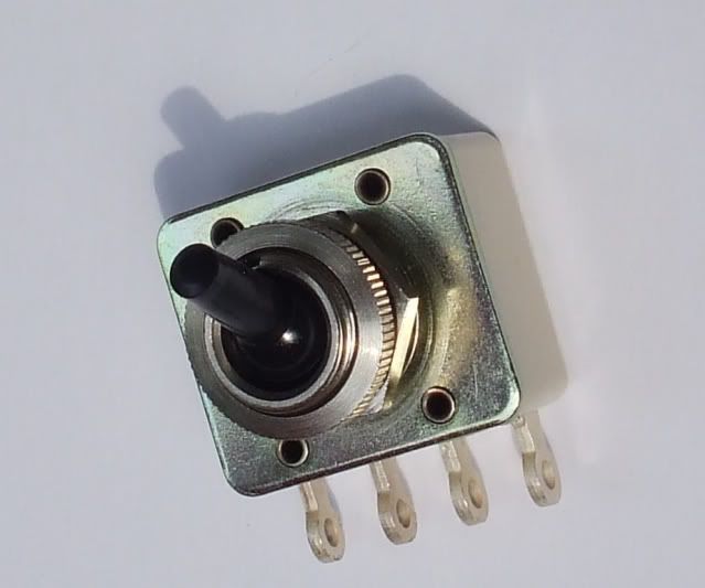
The two leftmost lugs are a pair, and the two rightmost lugs are a pair. WIth the switch open there's no continuity between either lugs. With the switch closed, 1 and 2 are connected, and 3 and 4 are connected.
JTM45 RS OT, 1973 18W, JTM45/100, JTM50, JMP50 1986, JMP100 "West Coast", AC15, AC30, BF Super Reverb, Boogie Mk 1, Hiwatt CP103, DR103

Fever Dog
Senior Member
Posts: 164
Joined: Tue Sep 25, 2007 10:54 pm
Contact:

Re: Castelco switch wiring?

Post by Fever Dog » Thu Aug 16, 2012 3:36 pm

Thank you
http://www.myspace.com/bigterrible" onclick="window.open(this.href);return false;

Post Reply