I downloaded all of Homebelly's layout diagrams, the problem is that I don't know which one is the final test-proven layout.
Too bad the pictures on all the old JTM100 build threads can't be displayed anymore...
JTM100 Black Flag vs. JMP100
Moderator: VelvetGeorge
-
Elad E
- Senior Member
- Posts: 137
- Joined: Sat Jun 29, 2013 9:19 am
- Just the numbers in order: 13492
-
neikeel

- Senior Member
- Posts: 7231
- Joined: Tue Dec 06, 2005 8:31 am
- Location: Suffolk, England
Re: JTM100 Black Flag vs. JMP100
http://www.flickr.com/photos/homebelly/7001479089/
http://www.flickr.com/photos/homebelly/7001479089/
Sorry forum will not open direct link
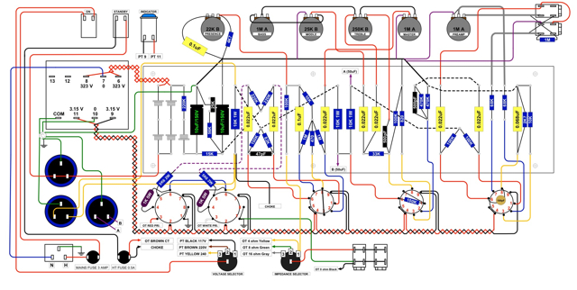
This one is close, you can work out the screens and PI hook ups, and the OT centre tap feed to the same turret as the choke.
http://www.flickr.com/photos/homebelly/7001479089/
Sorry forum will not open direct link
This one is close, you can work out the screens and PI hook ups, and the OT centre tap feed to the same turret as the choke.
Neil
-
Elad E
- Senior Member
- Posts: 137
- Joined: Sat Jun 29, 2013 9:19 am
- Just the numbers in order: 13492
Re: JTM100 Black Flag vs. JMP100
thanks, that is great!
Just to make sure, mentally "superimposing" this layout over my Superlead build - one of the right pair of caps (number 3 or 4 in the diagram) makes up the PI filtering and connects to the dropping resistor's turret which is closest to the back end while the screens filter caps pair connect to the opposing turret of the same dropping resistor?
Does it matter which pair of 32uf caps on the right goes to PI and which to the screens?
Last edited by Elad E on Thu Jan 18, 2018 10:22 pm, edited 1 time in total.
-
neikeel
- Senior Member
- Posts: 7231
- Joined: Tue Dec 06, 2005 8:31 am
- Location: Suffolk, England
Re: JTM100 Black Flag vs. JMP100
Normally the first 4 cans are mains, second two are screens and the next two PI.
Which end of the 8k2 resistor on the board you hook them up to will depend on how you run your board bus wire.
Conventionally the screens have yellow wire and if you look at the schematic they get B+ first (together with the skinny black wire from the other end of the choke - 1st choke wire goes to the OT CT and a yellow wire goes to pin 6 of the nearest octal and jumpers to the other pin 6s (with 1k 3w resistors to pin 4).
The blue PI node wire goes to the other end of the 8k2, together with the link wire that goes to the PI plate resistors (joint of the 82k and 100k) and then on off the board to the filter cap + on the board.
You have to take care to note which way your bus wires go, there are 2 ways to wire them, if you look at different layouts.
Neil
-
Elad E
- Senior Member
- Posts: 137
- Joined: Sat Jun 29, 2013 9:19 am
- Just the numbers in order: 13492
Re: JTM100 Black Flag vs. JMP100
In all photos of the 8 cap can 10 series amps (Black Flags and early JMPs) I have only encountered a bus wire layout identical to Homebelly's diagram that you linked to your previous post.
Could you please reference a pic of the other buss wire layout?
Could you please reference a pic of the other buss wire layout?
-
neikeel
- Senior Member
- Posts: 7231
- Joined: Tue Dec 06, 2005 8:31 am
- Location: Suffolk, England
-
Elad E
- Senior Member
- Posts: 137
- Joined: Sat Jun 29, 2013 9:19 am
- Just the numbers in order: 13492
Re: JTM100 Black Flag vs. JMP100
I must be missing something - it seems the leftmost bottom cap (Screens+PI) in this 50 watt amp (modified 2204?) is wired the same way and both halves, and the neighbouring preamp and mains caps, are grounded to the same point effectively identical to the JTM100 power board.
Whats the difference and how is applied to a black flag JTM100's power board?
Whats the difference and how is applied to a black flag JTM100's power board?
-
neikeel
- Senior Member
- Posts: 7231
- Joined: Tue Dec 06, 2005 8:31 am
- Location: Suffolk, England
Re: JTM100 Black Flag vs. JMP100
I only posted that pic to answer your specific question on the two different types of bus wire for the PI and screens, I have not looked at the rest of it and would not trust it. Joe does good stuff but I would stick with what I knew.
Just look at the way some amps have the bus wire for PI plate feed coming from the control panel side of the board - that is all.
Just look at the way some amps have the bus wire for PI plate feed coming from the control panel side of the board - that is all.
Neil