The FM Tube Modulator Jimi Loved
Moderators: VelvetGeorge, BUG
-
Xplorer

- Senior Member
- Posts: 2480
- Joined: Sun Apr 19, 2009 5:27 pm
- Just the numbers in order: 7
Re: The FM Tube Modulator Jimi Loved
sure, i was just curious to know if JC liked this kind of regeneration effect 
-
Eb7+9

- Senior Member
- Posts: 105
- Joined: Wed Mar 09, 2011 1:30 pm
- Just the numbers in order: 13492
- Contact:
Re: The FM Tube Modulator Jimi Loved
feeling like a locomotive plowing thru the snow, ...

finally got the board back for the single octave OTA modulator and Lattice
( ... see sims and discussion above)
looked at this PCB and realized even more how big a fella the full four or five octave emulation would be ...
it would mean 4 or 5 such cards ... big box kinda thing
let's call that the CRAZY-DIY'er version
there was a point to it // a master speed control option ...
also, the OTA's provide perfect summing at their outputs
something that can't happen (without losses) in the original Vacuum Tube Baldwin unit, or any class-A equivalent ...
so, the OTA's would offer a possibly more modern (and maybe more effective) final product
certainly something cool to investigate
I became even more curious about that aspect of it that when I realized the idea
I was using for our three-phase OTA modulator
could be used to embody a two-phase Fender "Harmonic" Vibrato effect
I didn't hesitate to invest the time to build one and check out a proof in action
besides, the circuit has a certain simplicity to it // providing a good bang for the buck
indeed it does ...
in my mind it was something just begging to happen
simply because the output current of an OTA
is "MADE to be summed" with the output of another ... (!)
almost an Engineer joke there, ... (ka-ching) ...
https://en.wikipedia.org/wiki/Kirchhoff's_circuit_laws
above you can well hear what that perfect Kirchoff summing can do for us
it's the only circuit I've ever designed that makes use of KCL like that
so, anyway ... that little side trip two weeks ago made me think the CTP built on OTA's might do the same
like, providing really insanely deep effect ... (pushing it ... so to speak)
but then, I sat there thinking "who the heck was gonna want to build something like this ...?"
there's still parts matching // BJT's this time (much easier tho) ... and it's lots of work, and big boards ... and in multiples ...
yikes, probably with a really high failure rate, ...
etc etc ...
to be fair I thought that "jFET matching" would trump "overall simplicity"
but having the PCB in my hands made me feel like putting all that on the back burner
and re-considering the jFET approach more
I'm sure I'll get back to the OTA monster one day ...
---
... enter the 2n5457 n-channel jFET
roll back a bit, ... in about 2008, as I felt the need to do so I sat down and formally started writing a two-page letter that explains how to "accurately" characterize jFET devices // what took so long for me to finish this work was not knowing what I would use these devices for as it wasn't for building yer typical Phasors as I much prefer optical ones to jFETs (for the headroom) ... but also, as a sort of goofball academic, the overall lack of good jFET understanding/teaching was something that had bugged me for a long time, even in school I noticed a strong lack of coverage in this area ... of course, part of it is because jFET math turns ugly when you stick the device in a differential pair arrangement, and the like ...
at the time I was charged with editing Sedra-Smith's third edition book in prep for the fourth edition and noticed how the jFET section paled in comparison to the BJT and MOS devices // if you have a copy take a look at the jFET differential pair section for example ... it's like a ghost-town inside the book
just for the fun of it I did some snooping around recently to see and found that pretty much all online tutorials (even those from academic institutions) are doing little more that copy what they've read in textbooks // I notice a similar thing with music theory books and how-to's ... I would say, basic theory aside, they even miss the mark when it comes to teaching how to design with jFET devices (yeah, I wrote something about that too but not releasing yet) // the methodology isn't there ...
Maybe it's because the IC industry an researchers tend to work more with BJT and MOS devices ... maybe it's becayse jFET devices are susceptible to a very broad 2-Dimensional variance range // something most people don't want to trouble themselves with ...
when I started on the CTP I had a funny feeling this to be the circuit for which I had started all that jFET-MATH stuff for, ...
but, having some doubts about the feasability and effectiveness of a jFET approach (esp. the potential need for matching) at first I thought that maybe going OTA would be easier ...
I'm thinking it might be the other way around now
but, only because now I have a large lot of available jFET's ...
and I characterized each and every one of them in the last month or so
I think that puts me in a somewhat unique position right now
something I'd like to see change
---
so, to this end ... back to present // in the last week or so I decided to revisit my paper and go thru my full collection of 2n5457 n-chan jFETs ... around 250 devices or so // random lots that I bought here and there over time
and tabulate the suckers in terms of accurately-extimated value of Vp and Idss under to\ightly controlled conditions
as you'll see there's very little you can do well by simply taking a chance with jFETs
unless you're building a clipping circuit or the like
that's why they were never too popular when building simple audio gain stages
BJT's usually preferred
in our case, as I shown above, we'll be needing tightly matched jFET devices
and not just loosely interpreted matching, but very specific in terms of Vgs(off) and Idss
which we all know have very wide tolerances in the datasheets,
... and, again, are also not very well explained in tutorials and textbooks (in my opinion ...)
in this regard, the best reference I could find talks about the parameters that go into making a full SPICE device model is a paper by NICULESCU and PARCARU
http://www.wseas.us/e-library/conferenc ... 63-159.pdf
notice the date on the paper, obviously the editors felt a need to be publishing something so basic on a creation that is not new ... now, as far as we're concerned if we're going to use jFET's to emulate the 12au7 Baldwin oscillators we need to understand what the similaritites and differences are
many DIY'ers obediantly repeat the mantra "jFETs are like Triodes" ... well, no that's not right ... if anything jFETs are more like Pentodes because of their similar Pinch-Off region ... Triodes don't exhibit pinch-off ... question is, does that make a big difference in the oscillator circuits ?? ...
SPICE to the rescue // it says that it doesn't ... so we're clear there
ok, another place where jFETs are quite different than both Triodes and Pendodes lies in its FIXED cut-off behavior ... jFET's always shut off when the Gate-Source voltage reaches Vp ... a.k.a Vgs(off) and Vth // as notated in datasheets and spice modeling, respectively ... that's completely unlike the case of both types of vacuum tubes, this voltage does not change with different supply voltages in jFET's / in tubes it does ... it is a hard limit fixed by the geometry of the jFET device, which contributes a higher sensitivity to device mismatch in some circuits
the bottom line is this, if we can make this circuit work well at all I feel it will be because we can produced 4 groups of tightly matched jFET triplets ... the simulations so far suggest gain variation and balanced behavior when this condition is met ... there is no need to do an audio simulation at this point as I can see the jFET circuit would modulate audio for the same reason the triode version does ... on to the build then
---
to answer this challenge, I needed to get some kind of probabilistic sense as to what we're up against here
and returned to my earlier characterizing work
spruced it up after mulling it over foor a long time and posted it at my blog
https://viva-analog.com/characterizing- ... ansistors/
out of 250 devices I counted 24 triplets ... we're talking about 10:1 ratio, but then again my lots are split in two major groups ... I don't even want to speculate on the odds
tho, ...
thanks to the internet, it may be a worthwhile thing for people to get into for sake of matching by posting their measurements somewhere ... starting a 2n5457 trading group
Happy holydaze and all that jazz-rock's ...
~jcm
Last edited by Eb7+9 on Tue Jan 05, 2016 7:36 am, edited 1 time in total.
modern VT circuit analysis and modeling: https://viva-analog.com/product/ifmta-book-pdf/
-
daveweyer
- Senior Member
- Posts: 713
- Joined: Wed Oct 29, 2014 9:36 pm
- Just the numbers in order: 13492
Re: The FM Tube Modulator Jimi Loved
JC, the tubes are actually cutoff devices too; the main thing is the transconductance at the point of cutoff. Tubes are characterized by cutoff characteristics, generally, sharp, remote and semi-remote.
Pentodes are actually very good for remote cutoff devices and in earlier days found extremely wide use as gain controlled amplifiers.
So both Jfets and tubes cutoff when the grid/gate voltage reaches a certain ratio with the grid/source voltage.
Again, the main thing you need is an extremely low transconductance at the point of cutoff; some tubes cut off very abruptly without a smooth transition--when they begin conducting they immediately have a sizable Gm.
These are not very suitable for variable gain amplifiers, the super high Gm devices usually fall into this category.
Great message by the way, lots of info.
Many thanks from all of us.
-
daveweyer
- Senior Member
- Posts: 713
- Joined: Wed Oct 29, 2014 9:36 pm
- Just the numbers in order: 13492
Re: The FM Tube Modulator Jimi Loved
That would be with the source/ cathode voltage by the way, in case you noticed my error.
-
Eb7+9
- Senior Member
- Posts: 105
- Joined: Wed Mar 09, 2011 1:30 pm
- Just the numbers in order: 13492
- Contact:
Re: The FM Tube Modulator Jimi Loved
hello all,
I finally got the 2n5457-based oscillators working and it was an interesting challenge to get them to even run ...
they will require some kind of switch/opto-circuit to start from power-up
leading to an interesting sort of kill/start arrangement
I blab about my testing/progress in this video:
https://www.youtube.com/watch?v=N0VCbmIsvJE
this does is a few things for us :

and, as a caveat, possibly leading the way to more accurate use of jFET's in other FX circuit ... etc,
but, I digress ...
---
for reference, the example shown in the video employed devices with the following (Vp, Idss) spec pairs :
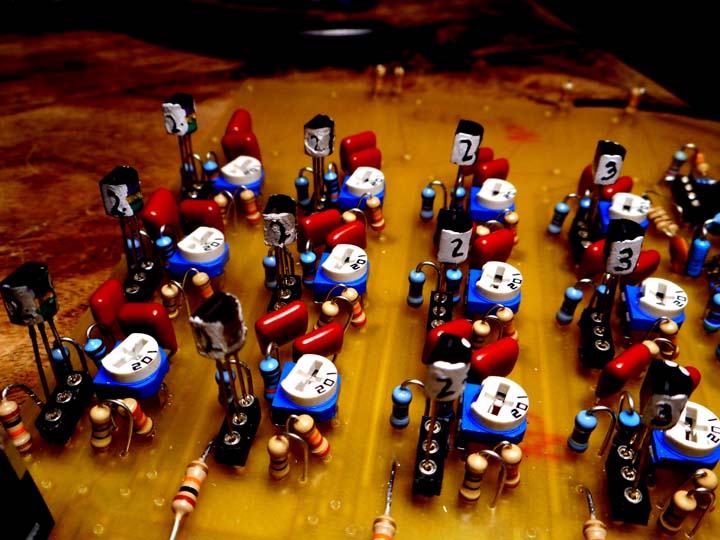
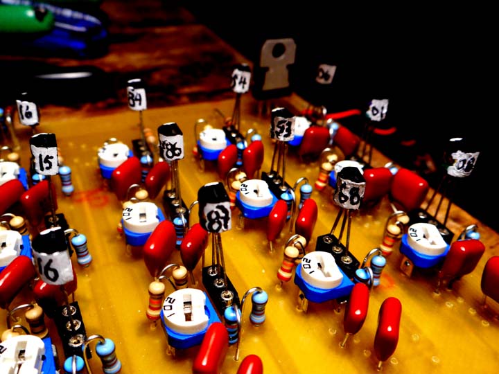
oscillator #1 (1Hz) : Vth = -1.13 volt // Idss = 2.01, 2.06, 2.08 mA
oscillator #2 (2Hz) : Vth = -1.33 volt // Idss = 2.53, 2.54, 2.68 mA
oscillator #3 (4Hz) : Vth = -1.41 volt // Idss = 2.84, 2.86, 2.87 mA
oscillator #4 (8Hz) : Vth = -1.43 volt // Idss = 3.15, 3.16, 3.16 mA
using some "white out" I drew the Idss value on each device ... (some way of keeping track of device groups)
X.YY mA ... X drewn on one side, YY on the other ...
as shown here :
http://www.lynx.net/~jc/LsideOscillatorJCM2015.jpg
http://www.lynx.net/~jc/RsideOscillatorJCM2015.jpg
---
as the "asymmetrical" simulation shows above, the parameter that seems to have priority is Vth
(as Idss is kept fixed in those sims)
in fact, they both play a role ...
so, devices with close Idss values, and near identical (+/-10mV) Vth are chosen in practice
seeing that we can assume all device Vth's are within +/- 5mV of the meter's reading on the scale chosen this means that device Vth values for grouped triplets are all within 10mV of each other // ... the limits of accuracy in this basic testing approach ...
not bad still, ... in fact, from the symmetry observed in the oscillator output (ie., in terms of phase-to-phase amplitude and shape) it would appear to be well sufficient for this task ... using bang-on close valued devices, and not, in Oscillator #1 made a considerable difference ... this leaves open the possibility of choosing devices sets against a desired or alternate wave shape ... I'm assuiming this is noteworthy as the the 1Hz would play a strong role here, and so would its shape // as I think Dave pointed out ... just thought it would be interesting to note
conclusion: this experiment suggests that my bench testing (with +/- 10mV accuracy on the interpolated Vth value) is sufficient in getting this oscillator to run with fair bit of symmetry and perpetual stability ... recalling that all this was deemed necessary as the fixed-cutoff jFET's do not function exactly the same way the variable-cutoff 12au7 oscillator triodes do in the the same topology ... now, that would be one heck of an analysis problem to fully describe
at this point it's easy to suggest some kind of chaotic behavior going on in there // we see it on the scope, even the simulations (with their inherent numerical noise) show this in action ... pretty cool // as unlike a perfect LFO as one could get ... again, somewhat similar to the Univibe LFO in that respect
---
one question that will come up : how many devices should one start with if they were to replicate these findings ...?!
consider that I used about 250 devices, and at the current (smallbear) price of $0.50
that amounts to $125 worth of transistors ... sounds a bit high
your mileage will vary as some of those were questionable devices purchased on eBay
while my Fairchild and National devices were bought years ago from SB ...
however, this does not preclude purchasing "questionable" devices on eBay
if they are all "counterfits" from a common lot, and they show collusion of specs during testing
then, no reason not to use them ... jFET specs are all over the place anyway
the exact specs don't seem to matter too much as long as they are about -1.55v and lower
it would seem that with higher threshold voltages one would need a correspondingly higher supply voltage
FYI, we cannot be sure of an exact range for 24vdc operation at the moment ... still early in the game
it's your call as to what you use for devices ... this is preliminary stuff anyway
I'm hoping others will chime in with their own results and add to what I'm providing here for details
maybe device pooling will need to happen before we see good results broadly speaking ...
who knows, ?
---
question that will obviously come up is, can we make the circuit run with un-matched devices ...??
I'm sure some people will find a lucky combination that will give some semblance of even operation
and like I mentioned above, asymmetrical operation might lead to cool textures,
we'll see ...
---
PLEASE TRY THIS AT HOME ...!!!
those interested now have the green light to breadboard an oscillator with confirmed circuit values :
now, onto PART 3 ... let's get the last caps and coils in there and have some audio pumping thru this beast ..
~jcm
I finally got the 2n5457-based oscillators working and it was an interesting challenge to get them to even run ...
they will require some kind of switch/opto-circuit to start from power-up
leading to an interesting sort of kill/start arrangement
I blab about my testing/progress in this video:
https://www.youtube.com/watch?v=N0VCbmIsvJE
this does is a few things for us :
so then, it would appear that all that 2n5457 matching work wasn't done in vain ...* it verifies that the SPICE sims (using TINA-TI) were very close to emulating the real circuit, ...
* and if the simulations involving devices with mismatched Vth (+/-100mV) are accurate, without any reason to suspect otherwise, it would confirm the validity of the matching technique I proposed earlier ...
and, as a caveat, possibly leading the way to more accurate use of jFET's in other FX circuit ... etc,
but, I digress ...
---
for reference, the example shown in the video employed devices with the following (Vp, Idss) spec pairs :
oscillator #1 (1Hz) : Vth = -1.13 volt // Idss = 2.01, 2.06, 2.08 mA
oscillator #2 (2Hz) : Vth = -1.33 volt // Idss = 2.53, 2.54, 2.68 mA
oscillator #3 (4Hz) : Vth = -1.41 volt // Idss = 2.84, 2.86, 2.87 mA
oscillator #4 (8Hz) : Vth = -1.43 volt // Idss = 3.15, 3.16, 3.16 mA
using some "white out" I drew the Idss value on each device ... (some way of keeping track of device groups)
X.YY mA ... X drewn on one side, YY on the other ...
as shown here :
http://www.lynx.net/~jc/LsideOscillatorJCM2015.jpg
http://www.lynx.net/~jc/RsideOscillatorJCM2015.jpg
---
as the "asymmetrical" simulation shows above, the parameter that seems to have priority is Vth
(as Idss is kept fixed in those sims)
in fact, they both play a role ...
so, devices with close Idss values, and near identical (+/-10mV) Vth are chosen in practice
seeing that we can assume all device Vth's are within +/- 5mV of the meter's reading on the scale chosen this means that device Vth values for grouped triplets are all within 10mV of each other // ... the limits of accuracy in this basic testing approach ...
not bad still, ... in fact, from the symmetry observed in the oscillator output (ie., in terms of phase-to-phase amplitude and shape) it would appear to be well sufficient for this task ... using bang-on close valued devices, and not, in Oscillator #1 made a considerable difference ... this leaves open the possibility of choosing devices sets against a desired or alternate wave shape ... I'm assuiming this is noteworthy as the the 1Hz would play a strong role here, and so would its shape // as I think Dave pointed out ... just thought it would be interesting to note
conclusion: this experiment suggests that my bench testing (with +/- 10mV accuracy on the interpolated Vth value) is sufficient in getting this oscillator to run with fair bit of symmetry and perpetual stability ... recalling that all this was deemed necessary as the fixed-cutoff jFET's do not function exactly the same way the variable-cutoff 12au7 oscillator triodes do in the the same topology ... now, that would be one heck of an analysis problem to fully describe
at this point it's easy to suggest some kind of chaotic behavior going on in there // we see it on the scope, even the simulations (with their inherent numerical noise) show this in action ... pretty cool // as unlike a perfect LFO as one could get ... again, somewhat similar to the Univibe LFO in that respect
---
one question that will come up : how many devices should one start with if they were to replicate these findings ...?!
consider that I used about 250 devices, and at the current (smallbear) price of $0.50
that amounts to $125 worth of transistors ... sounds a bit high
your mileage will vary as some of those were questionable devices purchased on eBay
while my Fairchild and National devices were bought years ago from SB ...
however, this does not preclude purchasing "questionable" devices on eBay
if they are all "counterfits" from a common lot, and they show collusion of specs during testing
then, no reason not to use them ... jFET specs are all over the place anyway
the exact specs don't seem to matter too much as long as they are about -1.55v and lower
it would seem that with higher threshold voltages one would need a correspondingly higher supply voltage
FYI, we cannot be sure of an exact range for 24vdc operation at the moment ... still early in the game
it's your call as to what you use for devices ... this is preliminary stuff anyway
I'm hoping others will chime in with their own results and add to what I'm providing here for details
maybe device pooling will need to happen before we see good results broadly speaking ...
who knows, ?
---
question that will obviously come up is, can we make the circuit run with un-matched devices ...??
I'm sure some people will find a lucky combination that will give some semblance of even operation
and like I mentioned above, asymmetrical operation might lead to cool textures,
we'll see ...
---
PLEASE TRY THIS AT HOME ...!!!
those interested now have the green light to breadboard an oscillator with confirmed circuit values :
BEST OF LUCK to those willing to give it a go ...!!10Meg to ground on the Gates, 1k trimmer to ground on the Sources (set just below half way), 3k9 and 10k Drain loads as per the Baldwin circuit, 100k bleeders, and caps >> 1Hz: 100nF shunt, 47nF series, 2Hz: 47nF shunt, 22nF series, 4Hz: 22nF hunt, 10nF series, 8Hz: 10nF shunt, 4nF series ... the whole works running off a 7824 regulator
now, onto PART 3 ... let's get the last caps and coils in there and have some audio pumping thru this beast ..
~jcm
modern VT circuit analysis and modeling: https://viva-analog.com/product/ifmta-book-pdf/
-
Eb7+9
- Senior Member
- Posts: 105
- Joined: Wed Mar 09, 2011 1:30 pm
- Just the numbers in order: 13492
- Contact:
Re: The FM Tube Modulator Jimi Loved
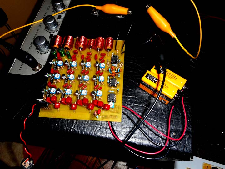
finally, ... IT"S ALIVE

http://www.lynx.net/~jc/CTPaudioJCM2015.jpg
notice the MAX1044 is gone ... the audio circuit is powered by two 9volt batteries now
---
initially, I wasn't getting anything detectable at the output
by using signal gen and scope I figured the TANK circuits were just sucking too much signal to GND
for example, there's 10k common load driving the output of the 3-phase oscillator/modulator block
goes thru a large-enough coupling cap and then the TANK circuit
if I'm reading the Baldwin schematic right the TANK values are
1H / 18uF ... 0.56H / 2.2uF ... 0.27H / .2uF ... 0.12H / 0.047uF
which resonate when their reactance are equal, ie. 2pi F L = 1 / 2pi F C
that is, ... 37.5Hz, 143.4Hz, 684.9Hz and 2.1k
and the reactance values are 235 ohmAC, 504 ohmAC, 1.1k ohmAC, and 1.6k ohmAC
no wonder ... after all, the tube circuit uses way larger signal swings ...
plus the two top frequencies are way outside the guitar's range of fundamentals
etc, etc ...
anyway, just to check things out I lifted the ground connections to the TANKs and stuck the circuit inside the FX loop of my modded Crate V50 to get a hotter input signal ... remember, this prototype version of the CTP has unity gain amplifiers in the LATTICE, unlike in the original ... just to see where the losses are ... by using a make-up gain preamp (Alesis microverb w input/output gains maxed) I was able to get a taste of what this thing can do ...
https://youtu.be/_WUEobHBLMk
well, Dave and gang ... waddaya think ??
all this work to explore a phase-shifting circuit that doesn't employ BBD's, opto elements or common OTA all-pass approaches
very cool if I may say ...!!
---
I don't know if it's too early to lay attributes
but the first down-side to this jFET approach is the lack of "continuous" speed control
Channels 2, 3, and 4 give an idea of what a signle channel operating at those speeds sounds like
obviously, like many//most Vibrato (Chorus WET channel) effects
it's good sounding, ... except maybe for some faint distortion ...
if manual speed control is ok (remenicent of the Maestro PS1) then you'd be ok here ...
tho, not so sure how that would play out ... there are six caps to swap here
and the need for tightly matched jFET's ... for a guitar or general instrument FX circuit
one modulator is probably sufficient // which means finding a single well-matched triplet of 2n5457's
probably doable within a lot of 50 to 80 devices (matter of luck)
but still ... beyond the skills and patience of many peeps
certainly not for beginners unfortunately // more like high expert zen torture master
and there was some perceptible distortion, though it's a little early to tell
simulations last night efinitely showed distortion ...
I would say this is something we don't see in the 12au7 stages, but more of a fact of life with jFET's
as we discussed above / still, it's not that terrible so far
anyway, don't want to kill the party ...
just some thoughts in passing
---
I'm going to take a break for a bit and get back to some other work
mull all this over
when I feel up to it I'll start on the single-channel OTA version // now that I know what to expect
thx Dave and all ...
cheers ... all the best in the new year folks !!
~jcm
Last edited by Eb7+9 on Sat Jan 02, 2016 11:12 pm, edited 2 times in total.
modern VT circuit analysis and modeling: https://viva-analog.com/product/ifmta-book-pdf/
-
Tek465b
- Senior Member
- Posts: 210
- Joined: Sat Jan 10, 2015 9:43 am
- Just the numbers in order: 13492
- Contact:
Re: The FM Tube Modulator Jimi Loved
Wow beautifull sound, and awesome work!.
I see alot of potential with it. Definatly something i need to get someday.
I see alot of potential with it. Definatly something i need to get someday.
-
Xplorer
- Senior Member
- Posts: 2480
- Joined: Sun Apr 19, 2009 5:27 pm
- Just the numbers in order: 7
Re: The FM Tube Modulator Jimi Loved
amazing work ! an inspiration for tenacity !!
Happy new year everyone !
Happy new year everyone !
-
daveweyer
- Senior Member
- Posts: 713
- Joined: Wed Oct 29, 2014 9:36 pm
- Just the numbers in order: 13492
Re: The FM Tube Modulator Jimi Loved
Yeah! Very cool. I can hear a certain signature which I recognize, even without the filters.
It's especially cool considering the extremely sharp cutoff characteristics of the Jfet. You found a way to make them work in your circuit. I look forward to further experiments. New Year, it is the return of the light, especially important for us up here in Montana.
It's especially cool considering the extremely sharp cutoff characteristics of the Jfet. You found a way to make them work in your circuit. I look forward to further experiments. New Year, it is the return of the light, especially important for us up here in Montana.
-
Eb7+9
- Senior Member
- Posts: 105
- Joined: Wed Mar 09, 2011 1:30 pm
- Just the numbers in order: 13492
- Contact:
Re: The FM Tube Modulator Jimi Loved
Montana, eh ... well, yippe eye otayay ...!!
(harr ...)
I apologize to those who might be a little confused,
the last video clip was meant more for Dave
as an example of what the 100% pure WET channel sounded like on its own
(and to show the thing making some sound)
so we can compare to units in 100 % pure mode, ... and tell how close the emulation is running
not at all how most guitarists, or William Wayne for that matter, would use a Chorus effect ...
of course not ... that was just part of the testing process
(well, maybe Syd Barrett would actually ...)
but anyway ...
now, ...
THIS is more like the intended SPATIAL setup // the "stereo" Performance Setup :
https://youtu.be/380nTUaRitQ
==================================================================================
explaining the "noise" side of things
this setup is analogous to what Dave described originally
well, to be fair, Dave said something about coming off the speaker to feed the CTP unit
I prefer going out the FX loop because there's typically less hum there
SPKR jacks, esp. when grounded directly to the metal chassis can be hummy ...
but, not matter ... as long as there's no hum either will work here
it's a similar idea ... basically using a strong signal to feed the CTP circuit
now, I was worried I was going to get lots of distortion
but I didn't ...
turns out I had a loose connection at the input, from all the tugging and twisting ...
I'm happy to report there is NO distortion at all when running the unit from the FX loop feed of my tube amp
and playing hard ...
to give an idea ... I'm running the preamp and lattice circuits off +/- 9 volt batteries
so, probably getting at least +/- 7 volts of headroom (I need to check the OPA2134/OPA134 datasheet to confirm)
anyhow, that's at least 14 volts pk-pk ... way more than LOTS of signal ...
(to give a relative idea, Fender BF 12at7 PI circuit clips at around +/-6 volts)
so, the oscillator/modulator block is the likeliest place to bottle-neck
I'll have to pull out my signal generator and scope to get an exact number
first impressions: I'm very pleased with the response, I tried pumping strong signal thru the thing
and, no problem ...
the passive summing network at the output is just like in the Baldwin unit, and fine as is
no need to make that active and add noise ... Zout of 22k is not too bad anyway
so, again, good condition for helping keep induced noise down in the "send" line ...
---
about the TANK circuits ...
I've given it a little thought after playing the unit this way ...
I think for guitar (bass/keyboards/sax etc ...) we're going to want the output running flat the way I have them now
maybe, in an augmented version meant for keys/organs someone can explore the "full" version
but seeing the amount of attenuation I was getting at first with them wired in
and also seeing how great the thing sounds as is, I've decided it's best to leave the circuit this way
and put that aspect of Wayne's invention out of the picture for us
hope, ya'll not too bummed out ... but for me this is a great place to rest for a bit
I want to say that this test also confirms that running the front end and lattice at unity gain throughout
works well and give sus good performance ... ie., can handle the strong signal of an FX loop line
AND not require extra boosting before going (at least) to another guitar amp (ie., no additional preamp boosting)
as it is now, having the TANK circuits in there would require additional boosting
and therefore result in more noise ...
either way, I think that the TANK frequencies are not very appropriate for guitar/bass anyway ...
I hope that explains my thought on the TANK circuits //
certainly, I would like to see somebody solve this problem
but for now, I'm leaving them out and running the output circuits at full bandwidth ...
back to the noise thing ...
the idea is to use a strong signal to get a really strong output
yielding good S/N ...
(remember, this was part of the presentation above)
and by removing the TANK circuits and running the outputs at full bandwidth
we get that nice strong output signal ... and a very pronounced effect
for guitar, this could be a very OK approach to take // Dave waddaya think ...?
notice another thing that happens when running on larger signals
the circuit is lying in free air on top of the amp and adding hardly any hum to the signal
that's impressive ...!!
same goes for hiss (white noise) ... I'm getting phenomenal thermal noise specs from this circuit
and, again, no discernible transient/dynamic distortion
I think Dave said this thing works well with distorted sounds ...
tho, I didn't try yet I can tell by how it reacts to the guitar dynamics right away
it's good
looking fwd to trying this thing with some old Marshalls ...
dang ... all around, noise/transient-reponse/effect-quality = win-win-win ...
============================================================================================
btw, I'm thinking of releasing a revised board or two for this project // a CTP-Mini (1 channel) and CTP-Std (4 channel) board for public DIY release ... I don't mind sharing the PCB layout so peeps can etch their own boards // I might make PCB boards available at my site if there's any interest ...
============================================================================================
anyway, NOW I'm pretty blown away with the quality of the sound ... !!
and we can do something that std. BBD-Chorus circuits can't do // ie., process large signals ...
and therefore, operate a real low noise
(*!*)
and, fortunately ... I can even turn on/off each oscillator and have them running in different combinations
a bonus by-product of the approach ... (luck o' the draw)
very cool option, in fact ...
having multiple oscillators running out of sync like this really brings out the analogue
I'd hate to see somebody try to program this in digital ... // this is a truly unique analogue circuit design
feeling lucky things worked out this well ...
~jcm
modern VT circuit analysis and modeling: https://viva-analog.com/product/ifmta-book-pdf/
-
Xplorer
- Senior Member
- Posts: 2480
- Joined: Sun Apr 19, 2009 5:27 pm
- Just the numbers in order: 7
Re: The FM Tube Modulator Jimi Loved
Wow !! it's just perfect, you've made it ! congrats it's a beautiful sound.
but why did you start with the oscilator 2, and skipped the #1 ?
but why did you start with the oscilator 2, and skipped the #1 ?
-
Tek465b
- Senior Member
- Posts: 210
- Joined: Sat Jan 10, 2015 9:43 am
- Just the numbers in order: 13492
- Contact:
Re: The FM Tube Modulator Jimi Loved
OMG i really need to get one of these now.
Definatly has ALOT of potential.
Definatly has ALOT of potential.
-
Eb7+9
- Senior Member
- Posts: 105
- Joined: Wed Mar 09, 2011 1:30 pm
- Just the numbers in order: 13492
- Contact:
Re: The FM Tube Modulator Jimi Loved
good question Xplorer ...Xplorer wrote:Wow !! it's just perfect, you've made it ! congrats it's a beautiful sound.
but why did you start with the oscillator 2, and skipped the #1 ?
the set of transistors I have in oscillator #1 at the moment aren't giving me a gd waveform ...
I had another set in there before that did, but haven't gone back to them yet
just left things as they are for illustration purposes
I found that #1 was making things a little jumbled
so left Osc#1 out of the picture in the last demo to see what would happen ...
incidentally, leaving the TANKs out in the output circuits leaves us open to exploring these options
where, maybe not so much with the Baldwin unit ...
also, I'm wondering if we're really only hearing osc #1 and #2 in the Baldwin unit, because the other
two oscillators (3 & 4) are operating more in the range of higher harmonics ...
conjecture ... (?!)
I will go back to Osc#1 when I have time and explore more
notice, one thing I didn't try yet : running #2 and #4 together ...
consider the following possibilities here for a moment:
one could potentially wire up 12 oscillators running a incrementally faster speeds
and mix them in more ways than I have ...
or, in all sillyness, using a 12-pos rotary switch to select between outputs to produce
a close-to-continuous speed controlled single-channel unit ... yeah, that's just plain silly ...
better figure out another way to introduce "continuous" speed control instead // ... that would be cool
for now, just checking things out as they arise in the present circuit ...
being able to switch Osc's on/off individually is useful as it produces a different quality effect
in fact, if you notice ... having only one oscillator working (#2 ~ 1.4Hz) makes a nice sounding effect nonetheless
hence my idea of making a single-channel board for those who feel they'd be happy with that
which, in that case, really comes down to only finding one matched triplet of jFETs
as opposed to four sets, which ='s monumental amount of testing and organizing
besides all this, I could also make it a mono device with internal mixing, as in the case of a typical stompbox
only one amp would be used then (not the full effect, but maybe ok ...)
still checking out the possibilities the circuit has to offer ...
~jcm
Last edited by Eb7+9 on Sun Jan 03, 2016 4:24 pm, edited 6 times in total.
modern VT circuit analysis and modeling: https://viva-analog.com/product/ifmta-book-pdf/
-
Eb7+9
- Senior Member
- Posts: 105
- Joined: Wed Mar 09, 2011 1:30 pm
- Just the numbers in order: 13492
- Contact:
Re: The FM Tube Modulator Jimi Loved
Hi Tek,Tek465b wrote:OMG i really need to get one of these now.
Definatly has ALOT of potential.
yeah - that's what I'm thinking too ...
pls let us know your progress if you are going to build one
I think I may have found an alternate means of matching jFET's that will still do for our needs here ...
ie., it won't give you a number for Vth but it will bracket the limits just the same
and make the 3-phase oscillator behave in a more balanced manner
ask, and I will explain ...
of course, I do invite peeps to breadboard the circuit and randomly stick their un-tested jFET's in there to see ...
you might get lucky, who knows ? ... and, a whobbly oscillator might sound interesting ...
I do recommend having a scope on hand ...
tho, not a completely impossible build without one
---
today, I'm gonna get to work on a more "pro" version
with slowed down shorting switches so there is no pop when engaging the oscillators
just snazzing it up little ...
I've also figured out a very simple way to do effect bypassing while keeping the output level the same
as opposed to merely "killing" the send signal to the second amp and suffering a volume drop
(wasn't sure how it should work in a live setting)
I'm also thinking of figuring out a way to get LED's blinking to each oscillator
almost a necessity, esp. at first ...
bells and whistles ... 'tis the season
~jcm
modern VT circuit analysis and modeling: https://viva-analog.com/product/ifmta-book-pdf/
-
Xplorer
- Senior Member
- Posts: 2480
- Joined: Sun Apr 19, 2009 5:27 pm
- Just the numbers in order: 7
Re: The FM Tube Modulator Jimi Loved
if it's as easy as building a fuzz, why not ?Eb7+9 wrote: in fact, if you notice ... having only one oscillator working (#2 ~ 1.4Hz) makes a nice sounding effect nonetheless
hence my idea of making a single-channel board for those who feel they'd be happy with that
which, in that case, really comes down to only finding one matched triplet of jFETs
as opposed to four sets, which ='s monumental amount of testing and organizing
seriously, maybe one day because it's worth it. for now, i don't even know how to match the jfets and i may not have the right Tools for this.
thanks for the idea and for the offer.