Jimi Hendrix' Gear and Mods at West Coast Organ and Amp
Moderators: VelvetGeorge, BUG
-
Xplorer

- Senior Member
- Posts: 2471
- Joined: Sun Apr 19, 2009 5:27 pm
- Just the numbers in order: 7
Re: Jimi Hendrix' Gear and Mods at West Coast Organ and Amp
looking great !
-
antosimoni

- Senior Member
- Posts: 498
- Joined: Wed Jul 12, 2006 9:45 am
- Just the numbers in order: 7
- Location: Fl
Re: Jimi Hendrix' Gear and Mods at West Coast Organ and Amp
can you please tell how do you make the wah work with the fuzz? I got constant squeals...bill bokey wrote: ↑Fri Oct 21, 2016 2:31 pmHere's a video of the SLP I modded to West Coast specs, with a (modded) JH-F1 Fuzz Face and a (modded) vintage King Vox Wah :
in loudspeakers we trust
-
daveweyer
- Senior Member
- Posts: 713
- Joined: Wed Oct 29, 2014 9:36 pm
- Just the numbers in order: 13492
Re: Jimi Hendrix' Gear and Mods at West Coast Organ and Amp
If you have the wah first in the chain, it can short out the feedback in the fuzz and cause too much gain; it happened to Jimi when he first started using the wah. A 10K resistor on the output of the wah can help.
-
daveweyer
- Senior Member
- Posts: 713
- Joined: Wed Oct 29, 2014 9:36 pm
- Just the numbers in order: 13492
Re: Jimi Hendrix' Gear and Mods at West Coast Organ and Amp
Tek, if you didn't catch the note on the 6550 thread, I got the 2N591s and the 2N725s. Send me a PM and tell me where I should ship them. Board looks just super.
-
antosimoni
- Senior Member
- Posts: 498
- Joined: Wed Jul 12, 2006 9:45 am
- Just the numbers in order: 7
- Location: Fl
Re: Jimi Hendrix' Gear and Mods at West Coast Organ and Amp
thanks, its same as here (although here its a 1K)?:
[youtube]https://www.youtube.com/watch?v=u6_DCjR67Uw[/youtube]
in loudspeakers we trust
-
daveweyer
- Senior Member
- Posts: 713
- Joined: Wed Oct 29, 2014 9:36 pm
- Just the numbers in order: 13492
Re: Jimi Hendrix' Gear and Mods at West Coast Organ and Amp
I used a 1K on that circuit, yes, but feel free to try different values. By the time that prototype was built, we had changed the fuzz units too, and 1K was sufficient. I think 10K worked best on the stock units.
-
antosimoni
- Senior Member
- Posts: 498
- Joined: Wed Jul 12, 2006 9:45 am
- Just the numbers in order: 7
- Location: Fl
Re: Jimi Hendrix' Gear and Mods at West Coast Organ and Amp
I realized now you are the same person as in the vid, thanks for your info
Last edited by antosimoni on Sun Feb 11, 2018 3:18 pm, edited 1 time in total.
in loudspeakers we trust
-
daveweyer
- Senior Member
- Posts: 713
- Joined: Wed Oct 29, 2014 9:36 pm
- Just the numbers in order: 13492
Re: Jimi Hendrix' Gear and Mods at West Coast Organ and Amp
In the fuzz mods we added a resistor on the input, and the later mods had a 40K pot there, which gives you a nice range of fuzz intensity and tone, especially with a wah on the input.
Xplorer and Shakti, I found enough old transistors to get your fuzz units running. I'll send them to Tek once I get his address.
Xplorer and Shakti, I found enough old transistors to get your fuzz units running. I'll send them to Tek once I get his address.
-
Xplorer
- Senior Member
- Posts: 2471
- Joined: Sun Apr 19, 2009 5:27 pm
- Just the numbers in order: 7
Re: Jimi Hendrix' Gear and Mods at West Coast Organ and Amp
Coool !!!daveweyer wrote: ↑Sun Feb 11, 2018 3:03 pmIn the fuzz mods we added a resistor on the input, and the later mods had a 40K pot there, which gives you a nice range of fuzz intensity and tone, especially with a wah on the input.
Xplorer and Shakti, I found enough old transistors to get your fuzz units running. I'll send them to Tek once I get his address.
Tek, i'll send youa paypal for the board, let's see in pm. i didn't have the time to check what parts i have in my stock to complete some parts of yours. will do
-
Tek465b
- Senior Member
- Posts: 207
- Joined: Sat Jan 10, 2015 9:43 am
- Just the numbers in order: 13492
- Contact:
Re: Jimi Hendrix' Gear and Mods at West Coast Organ and Amp
Yes Dave please send me an e-mail or pm.
I will tell you my address and you can tell me how much it cost. i do have paypal and e-mail money transfer.
I want to buy a few of them for me and Roe(and maby more to make matched set for everyone else who got the pcb) if this is possible.
I will tell you my address and you can tell me how much it cost. i do have paypal and e-mail money transfer.
I want to buy a few of them for me and Roe(and maby more to make matched set for everyone else who got the pcb) if this is possible.
-
antosimoni
- Senior Member
- Posts: 498
- Joined: Wed Jul 12, 2006 9:45 am
- Just the numbers in order: 7
- Location: Fl
Re: Jimi Hendrix' Gear and Mods at West Coast Organ and Amp
Dave,
thanks a lot, but I need to ask 3 questions, please let me know:
1) if I put the 10K resistor at the input of the Fuzz Face, between jack and the 2.2uF (ref. silicon FF Fulltone 70) will it be the same (Id like to have the wah stock)??
2) the resistor/pot in series with the "input node" is in the same place as in my point 1)?daveweyer wrote: ↑Sun Nov 09, 2014 9:37 pm.. the first step at West Coast was to put a resistor in series with the input node of the first transistor. A 50K pot can give you a lot of variation. (I tried changing the feedback resistor, and even bypassing part of it with a film cap too, but the simplest way was to use a series input resistor)
...
What he lost in gain from the first transistor of the fuzz, would be made up by increasing the gain in the second transistor of the fuzz box. (increase the collector load resistor of the second transistor up to maybe 20K)
3) the "collector load resistor" of the second transistor is the pair of 5K trim + 1K resistor?
Thanks a lot for your help
layout:

in loudspeakers we trust
-
daveweyer
- Senior Member
- Posts: 713
- Joined: Wed Oct 29, 2014 9:36 pm
- Just the numbers in order: 13492
Re: Jimi Hendrix' Gear and Mods at West Coast Organ and Amp
Yeah, the input resistor/pot can go between the input jack and the 2uf cap shown on the board. Somehow I thought that the Fulltone had a resistor there, but I guess not in this circuit. The wah can be left stock when you have that resistor in place.
The second transistor collector load is the pot/trimmer and resistor. You can get the output signal from the wiper of that pot by connecting the cap there, it scratches when you turn it because the pot has DC across it, but the gain of the circuit referenced to the amp input can be made much higher. This holds if you use a larger pot too. This gives you a lot more amp input overdrive, and you can turn the fuzz down.
The second transistor collector load is the pot/trimmer and resistor. You can get the output signal from the wiper of that pot by connecting the cap there, it scratches when you turn it because the pot has DC across it, but the gain of the circuit referenced to the amp input can be made much higher. This holds if you use a larger pot too. This gives you a lot more amp input overdrive, and you can turn the fuzz down.
-
antosimoni
- Senior Member
- Posts: 498
- Joined: Wed Jul 12, 2006 9:45 am
- Just the numbers in order: 7
- Location: Fl
Re: Jimi Hendrix' Gear and Mods at West Coast Organ and Amp
thanks a lot, appreciate
in loudspeakers we trust
-
Tek465b
- Senior Member
- Posts: 207
- Joined: Sat Jan 10, 2015 9:43 am
- Just the numbers in order: 13492
- Contact:
Re: Jimi Hendrix' Gear and Mods at West Coast Organ and Amp
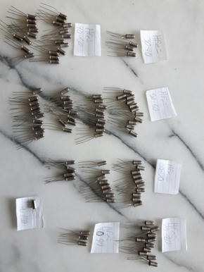
I got the RFT GS109C transistor(AC125 equivalent)
I did not test the leakage for all of them but the ones i tryed are very good and low(under 100-200µA)
Here are the quantity by HFe range:
HFe 30-40 = 4
HFe 40-50 = 21
HFe 50-60 = 39
HFe 60-70 = 22
HFe 70-80 = 11
HFe 80-90 = 3
HFe 90-100 = 1
I installed some transistor to try the circuit and see how it will bias(yes i did solder the germanium to the pcb, i hate sockets):
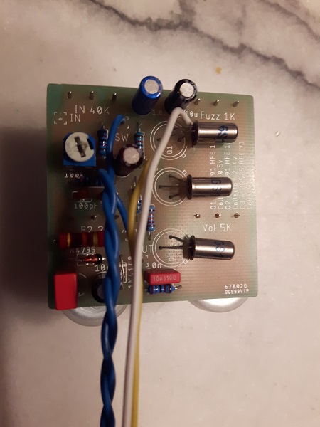
Diode that worked for me was the 5.6Volt Zener and removing the 1N4148 Diode(using a wire jumper instead)
For my own unit this is the transistor and bias setting that worked.
Q1C = 0.46V, HFe = 81, Leakage = 166µA
Q2C = 4.03V, HFe = 67, Leakage = 89µA
Q3C = 7.59V, HFe = 67, Leakage = 113µA
Bias Supply - Bias supply voltage = 6.09V
Bias OUT - Bias with 5.6Zener and no 1N4148 = 1.59V
Yes my HFe are lower, i think that only Q1 really matter(because of the input impedance change with HFe) so i set the higher HFe on Q1.
I also updated the webpage/instructions: Tek465B Website
I did not test the leakage for all of them but the ones i tryed are very good and low(under 100-200µA)
Here are the quantity by HFe range:
HFe 30-40 = 4
HFe 40-50 = 21
HFe 50-60 = 39
HFe 60-70 = 22
HFe 70-80 = 11
HFe 80-90 = 3
HFe 90-100 = 1

I installed some transistor to try the circuit and see how it will bias(yes i did solder the germanium to the pcb, i hate sockets):
Diode that worked for me was the 5.6Volt Zener and removing the 1N4148 Diode(using a wire jumper instead)
For my own unit this is the transistor and bias setting that worked.
Q1C = 0.46V, HFe = 81, Leakage = 166µA
Q2C = 4.03V, HFe = 67, Leakage = 89µA
Q3C = 7.59V, HFe = 67, Leakage = 113µA
Bias Supply - Bias supply voltage = 6.09V
Bias OUT - Bias with 5.6Zener and no 1N4148 = 1.59V
Yes my HFe are lower, i think that only Q1 really matter(because of the input impedance change with HFe) so i set the higher HFe on Q1.
I also updated the webpage/instructions: Tek465B Website
-
Tek465b
- Senior Member
- Posts: 207
- Joined: Sat Jan 10, 2015 9:43 am
- Just the numbers in order: 13492
- Contact:
Re: Jimi Hendrix' Gear and Mods at West Coast Organ and Amp
Am trying new method for enclosure finishing what are your input on this"the bottom cover/dark anodized"?(sorry for bad etching, i made absolutly no effort to make a good toner mask since this is just a test). The right side is sanded in the bottom picture.:
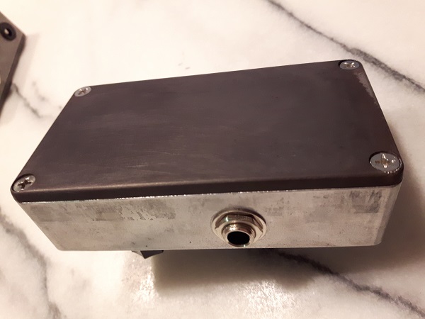
More detail on the process can be found here: https://tek465b.github.io/Page4.html
More detail on the process can be found here: https://tek465b.github.io/Page4.html