His guitar slung across his back, his dusty boots is his cadillac.
Moderators: VelvetGeorge, BUG
-
Xplorer
- Senior Member
- Posts: 2473
- Joined: Sun Apr 19, 2009 5:27 pm
- Just the numbers in order: 7
Post
by Xplorer » Sat Feb 07, 2015 7:24 pm
ha ha, i see what you mean , maybe i should improve this gift i perhaps have too because this is how i felt when almost the first thing i touched was the first bug. but i'm still a zero for this though

yeah, i'll check some voltages, i did it a bit already but not enough.
first thing i checked was the input / output wiring , and i noticed that i forgot the 0,05 uf cap before the 150k pot ( 250k in my case ) , but it shouldn't be responsible for a : no sound at all.
-
Xplorer
- Senior Member
- Posts: 2473
- Joined: Sun Apr 19, 2009 5:27 pm
- Just the numbers in order: 7
Post
by Xplorer » Sat Feb 07, 2015 7:57 pm
if i start from the voltage poles of the battery, it gets 8,86 volts
on one side of the 1,7 M combo ( one 1M5 + one 180k + one 250k trimmer, all in serie ) i get 7,5 volts , it's the side where it connects to the 1,5 uf going to the ground ( a non polarised 1uf on my build )
on the other side ( Q1 B side ) i get 0,12 volts.
Q1 E : 0 volts
Q1 B : 0,12 volts
Q1 C : 0,03 volts
Q2 E : 0,014 volts
Q2 B : 0,03 volts
Q2 C : 8, 2 volts
Q3 E : 8 volts
Q3 B : 8,2 volts
Q3 C : 8,1 volts
-
Tek465b
- Senior Member
- Posts: 207
- Joined: Sat Jan 10, 2015 9:43 am
- Just the numbers in order: 13492
-
Contact:
Post
by Tek465b » Sun Feb 08, 2015 9:08 am
Xplorer wrote:if i start from the voltage poles of the battery, it gets 8,86 volts
on one side of the 1,7 M combo ( one 1M5 + one 180k + one 250k trimmer, all in serie ) i get 7,5 volts , it's the side where it connects to the 1,5 uf going to the ground ( a non polarised 1uf on my build )
on the other side ( Q1 B side ) i get 0,12 volts.
Q1 E : 0 volts
Q1 B : 0,12 volts
Q1 C : 0,03 volts
Q2 E : 0,014 volts
Q2 B : 0,03 volts
Q2 C : 8, 2 volts
Q3 E : 8 volts
Q3 B : 8,2 volts
Q3 C : 8,1 volts
There is something wrong with Q3.
What ohm reading you get from Q3E to ground and from Q3C to vcc(-9volt)?
-
Xplorer
- Senior Member
- Posts: 2473
- Joined: Sun Apr 19, 2009 5:27 pm
- Just the numbers in order: 7
Post
by Xplorer » Sun Feb 08, 2015 1:43 pm
Hi !
thanks,
well, from Q3 E to ground ( output jack ground, where the positive pole of the battery is connected ) , i read 0 ohms
from Q3 C to negative connection : 7M5 ..
-
Tek465b
- Senior Member
- Posts: 207
- Joined: Sat Jan 10, 2015 9:43 am
- Just the numbers in order: 13492
-
Contact:
Post
by Tek465b » Sun Feb 08, 2015 3:23 pm
I dont see how the Q3E can be at 8v while it is shorted to ground. So that leave me stumped
If you can post a picture of the circuitboard , (both side if possible)and the output wiring that will help us.
Or just wait to see what Dave has to say, but i think picture will help him too.
anyway Q3E should be around 8k3, Q3C 1k.
-
Tek465b
- Senior Member
- Posts: 207
- Joined: Sat Jan 10, 2015 9:43 am
- Just the numbers in order: 13492
-
Contact:
Post
by Tek465b » Sun Feb 08, 2015 3:43 pm
Anyway what am thinking is, E and C of Q3 look to have a problem, and if that dont fix it maby you have too much bias current at Q1B.
edit are you sure the 1.5M is correct?
Can you measure resistance from the 100k/1.5u to the Base of Q1.
Last edited by
Tek465b on Sun Feb 08, 2015 4:14 pm, edited 2 times in total.
-
Xplorer
- Senior Member
- Posts: 2473
- Joined: Sun Apr 19, 2009 5:27 pm
- Just the numbers in order: 7
Post
by Xplorer » Sun Feb 08, 2015 4:02 pm
thank you,
i'm sorry to meet such bug. i didn't have the time to check the circuit step by step yet, if it's completely following the schematic or if it has a mistake somewhere.
here you can see some pictures, but it may be a hassle.
http://imgur.com/a/iPVSE
-
Tek465b
- Senior Member
- Posts: 207
- Joined: Sat Jan 10, 2015 9:43 am
- Just the numbers in order: 13492
-
Contact:
Post
by Tek465b » Sun Feb 08, 2015 4:52 pm
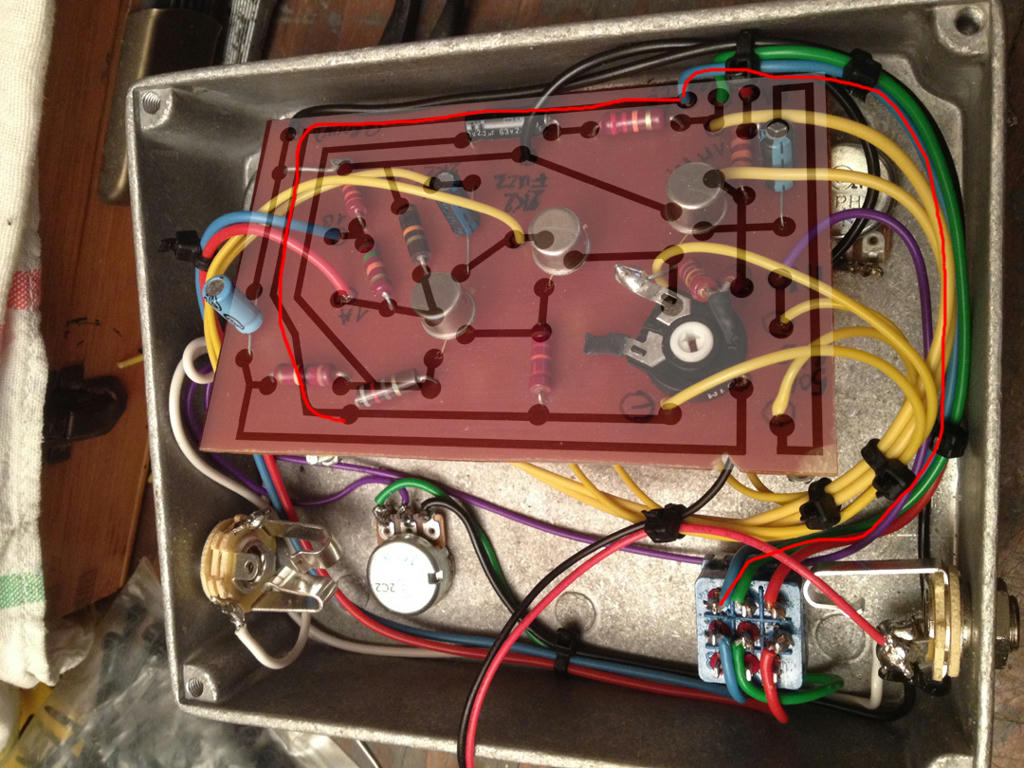
spotted an error on the pcb.
The nfb side of the switch.. remove the blue wire that is just above the 22k. that wire is giving tons of Bias current on Q1, it fuck everything up.
Am still looking at the pcb, iwill report if i find something else.
EDIT see the red stuff i added you need to break that contact(unsolder/remove the blue wire):
http://www.mediafire.com/convkey/b0dc/k ... 6raa6g.jpg
-
Tek465b
- Senior Member
- Posts: 207
- Joined: Sat Jan 10, 2015 9:43 am
- Just the numbers in order: 13492
-
Contact:
Post
by Tek465b » Sun Feb 08, 2015 5:15 pm
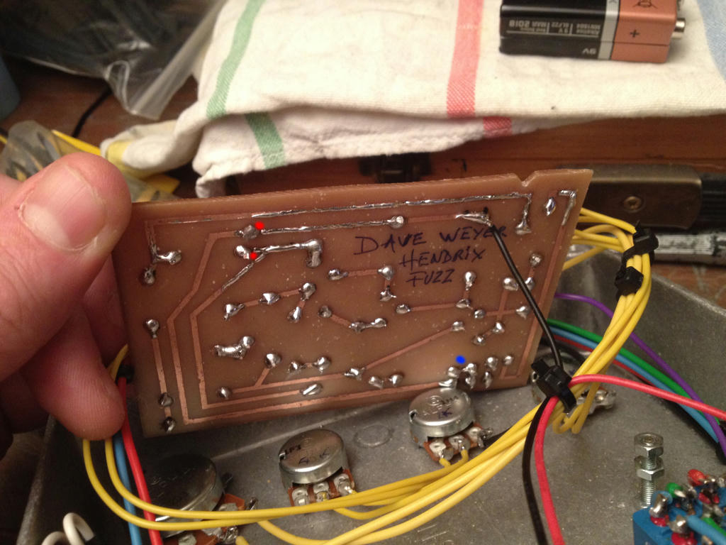
Also it look like you have some open trace on the pcb.
and
you have a solder bridge for that blue wire i spoken above and the green one.
in red is where i think there is an open and
in blue is where you need to remove the solder bridge,
http://www.mediafire.com/convkey/582b/m ... 3hsi6g.jpg
Last edited by
Tek465b on Sun Feb 08, 2015 5:18 pm, edited 1 time in total.
-
Xplorer
- Senior Member
- Posts: 2473
- Joined: Sun Apr 19, 2009 5:27 pm
- Just the numbers in order: 7
Post
by Xplorer » Sun Feb 08, 2015 5:17 pm
thanks a lot for watching ! with photoshop and all that, very cool

i thought that this connection ( blue wire ) was supposed to connect A to the point between the 22k and the 1M pot ... ( ? )
http://i.imgur.com/u5pVBTV.jpg
so A is going nowhere ?
the switch middle point between the red line and the blue line ( A ) is ( i thought it was this ? ) connecting either A ( near the 1k to the 1M / 22k point , OR the ..... mmmmh ...... 33k connected Q1 B on one side and to nithing on the other side , i see , i misunderstood the switch connections, but i don't get it yet.
-
Tek465b
- Senior Member
- Posts: 207
- Joined: Sat Jan 10, 2015 9:43 am
- Just the numbers in order: 13492
-
Contact:
Post
by Tek465b » Sun Feb 08, 2015 5:20 pm
Xplorer wrote:thanks a lot for watching ! with photoshop and all that, very cool
i thought that this connection ( blue wire ) was supposed to connect A to the point between the 22k and the 1M pot ... ( ? )
http://i.imgur.com/u5pVBTV.jpg
so A is going nowhere ?
the switch middle point between the red line and the blue line ( A ) is ( i thought it was this ? ) connecting either A ( near the 1k to the 1M / 22k point , OR the ..... mmmmh ...... 33k connected Q1 B on one side and to nithing on the other side , i see , i misunderstood the switch connections, but i don't get it yet.
No its not. that side of the switch is used only to switch the 33k on and off accross the 1m pot..
Like i said, remove that wire, and remove the solder bridge that short it to the green wire.
The way your doing it now send too much current on base of Q1 and it also short out the nfb to the Vcc rail.
If that 1m pot was at a low ohm setting, you probably burnt Q1.
-
Xplorer
- Senior Member
- Posts: 2473
- Joined: Sun Apr 19, 2009 5:27 pm
- Just the numbers in order: 7
Post
by Xplorer » Sun Feb 08, 2015 5:27 pm
thanks. in red it's actualy not open, i checked, but you're right, it looks like it. good eyes.
let me see , on one position, this part of the switch turns on or off the 33k in parallel with the 1M pot .
on the other position, it removes the 33k and connects A ( from the 1K ) to the point just before the 1M pot , am i right ?
about the bridge, i don't understand, isn't it the point where the middle point of the switch ( the green wire ) connects to the 22k AND the 1M pot on the schematic ? if i remove this connection, it won't be the schematic anymore, or am i missing something ?
-
Tek465b
- Senior Member
- Posts: 207
- Joined: Sat Jan 10, 2015 9:43 am
- Just the numbers in order: 13492
-
Contact:
Post
by Tek465b » Sun Feb 08, 2015 5:37 pm
see me reply in the quote.
Xplorer wrote:thanks. in red it's actualy not open, i checked, but you're right, it looks like it. good eyes.
let me see , on one position, this part of the switch turns on or off the 33k in parallel with the 1M pot .
yes, one side of the switch is used for that, and the other side is used to select the output from the 15k/35k for different output volume level)
on the other position, it removes the 33k and connects A ( from the 1K ) to the point just before the 1M pot , am i right ?
no
about the bridge, i don't understand, isn't it the point where the middle point of the switch ( the green wire ) connects to the 22k AND the 1M pot on the schematic ? if i remove this connection, it won't be the schematic anymore, or am i missing something ?
You dont have to remove the green wire, i did not say that.
Under the pcb, the green and blue wire are solder bridge together, this is a big problem.
There must be no connection from the green wire/22k-1M to the vcc(blue wire) at all in any position of the switch.
The way you have it now, the green wire/22k-1Meg are permanently shorted to the blue vcc wire. at lest it look like this from the picture.
-
Xplorer
- Senior Member
- Posts: 2473
- Joined: Sun Apr 19, 2009 5:27 pm
- Just the numbers in order: 7
Post
by Xplorer » Sun Feb 08, 2015 5:45 pm
Under the pcb, the green and blue wire are solder bridge together, this is a big problem
actualy it's not connected together, it's seperated.
http://www.mediafire.com/convkey/b0dc/k ... 6raa6g.jpg
on the other position, it removes the 33k and connects A ( from the 1K ) to the point just before the 1M pot , am i right ?
no
aah ok, but now i'm wondering : where is this A ( near the 1k ) going ? on the schematic it's going nowhere so ...
i thought that you confirmed to me previously that it should connect to the other switch position. maybe my imagination going wrong.
-
Tek465b
- Senior Member
- Posts: 207
- Joined: Sat Jan 10, 2015 9:43 am
- Just the numbers in order: 13492
-
Contact:
Post
by Tek465b » Sun Feb 08, 2015 5:47 pm
EDIT:
1k near point A go to nowhere.
There is no solder bridge my fault. but remove the blue wire
Last edited by
Tek465b on Sun Feb 08, 2015 6:02 pm, edited 4 times in total.
