thx Tek,
(ed.) ... just watched the youtube video //
explains perfectly what I'm doing here
that guy has a great approach to teaching basic electronics
yeah, ... 2-sided boards is all we need for this ... keeping it simple

we can get creative with the limitations // stacking cards if need be
when the time comes I will upload the .sch files
---
on the side ...
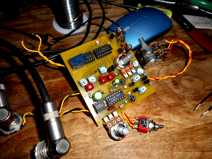
I spent a good part of the day on the bench ironing out issues in my newly designed
2x-OTA based Fender 6G-series Vibrato emulator/Xtender
to recall, it's operation is similar to what I've chosen as my first approach to producing a CTP emulator
turns out some high-frequencies were cycling around in there ... oops!
current-mode circuit operation tends to do that
so, I shunted down some bandwidth using a few caps and, voila ...
(*!*)
it works as good as can be expected ...
http://www.lynx.net/~jc/6GvibratoVOX.jpg
this is definitely
an FX loop circuit as OTA's tend to be a little noisy by nature...
glad to say its performance is more than passable, and am pleased with the outcome
but it has to be used correctly ... ie., not in front of an amp (preamp) like most of us use Phasors
as for function,
I have a switch on there that inverts the phase of the H.P. branch
so I can get L.P. and H.P. signal components variably summed either in-phase, or out-of-phase ...
(inducing no phasing effect, ... or some, respectively)
the original Fender circuit summed out-of-phase and therefore produced pitch shifting Vibrato/Phasing
it is not simply a matter of alternating L.P. and H.P. signals as some say
I'm not surprised by the amount of phasing/pitch-shifting obtainable from this OTA-based mixing circuit
FYI, at full swing the OTA bias currents travel between nil and about 1.2m (each) ...
(max is 2mA for LM13600 OTA's)
there's also a middle "off" position on the phase switch that acts to prevent any H.P. signal from making it thru
what i get then is an interesting sub 300Hz pulsing signal // Floydish sounds
very cool so far ...
in case anybody's wondering the two empty holes will be occupied
by 12-pos rotary switches for altering H.P.and L.P. corner frequencies
these will be made variable later // haven't decided on frequency ranges yet
at the moment both paths are set to a -3db cutoff of 300 Hz, as it is in the original Fender Vibrato circuit
the oscillator is based off a Univibe and the soft-switch slowly kills and releases the oscillator,
same as in the original Vibes ... except, i'm using a CMOS latching circuit and opto-isolator to do the kill
also, I have a jack on the side for a remote floor switch if I want to use one
anyway, I needed to get the basic operation established and secondary bugs taken out
that's done now ...
putting the Vibrato box aside for now ...
I'll get back to the two variable cap switches when I'm more in the mood for it
---
FYI,
to understand how one can get
passable Signal-To-Noise specs using noisy processing circuits
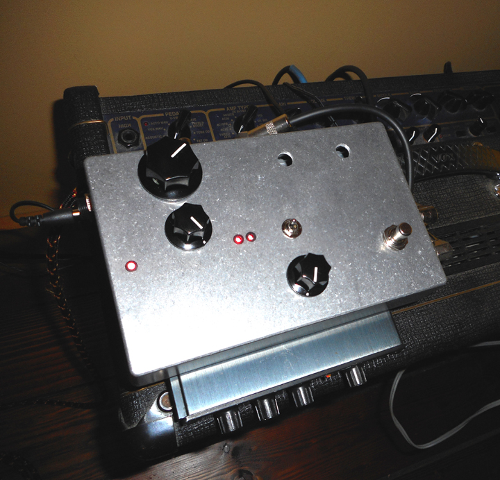
I present this as an example (see accompanying photo)
my gtr is going to an Alesis MicroVerb set very hot both in and out, it's acting as a preamp with no tone controls
then to my Vibrato circuit with the output set low (hot going in, just hot enough going out)
and to a recently gifted Vox Valvetronix, by using the Effects Return jack
(essentially bypassing all of the preamp and DSP)
the Master on the amp on 10 ...
so, the volume control on the Vibrato pedal is essentially setting the volume level of the whole setup
and at the same time, the overall noise level since its output dominates in terms of noise (a drawback of using OTA's)
the Microverb is very clean, the output stage of the VOX SS-amp is so-so clean ...
the vibrato circuit is noisy if we compare to modern chorus/phasors and the like
that's just the nature of modulated H.P. circuit and the OTA's used to modulate the signals
so, the best option is to run the other two (Alesis and VOX slave) as hot as possible
the result is excellent if we compare against
what happens if we reverse order the Vibrato circuit and Alesis preamp
to be clear, a big component of what makes this circuit noisy is the modulated H.P. circuit ...
we should note that the same occurs in the original Fender 6G-series tube amps ...(!!)
this is the main reason why we see the circuit sandwiched between the preamp and the PI circuit
in those 6G and 6G-A series Fender amps... ie., that is, to maximize the Signal-to-Noise ratio ...
which translates in less overall noise increase when the effect is running
that is, the signal (level) that normally drives the PI circuit is sent to the Vibrato stage
they could have done it the other way, but there's a good reason why they didn't
same as in my
Alesis >> 6G-Vibrato emulator/Xtender >> VOX Slave setup
what makes this all work is the fact that both vibrato circuits (the original tube one and this one)
have high-headroom capabilities ... I designed my circuit to handle +/- 5 volts of signal swing with low distortion
(and not using the linearizing diodes either)
I think this is appropriate for most tube driven PI circuits ... actually a 12at7 based PI circuit may need a little more
so, this thing should work in tube amps that have FX loops // sometimes a useful option even tho most of us typically like the Phasor up front ... ie., for those times when the overall signal isn't so dirty
all this, just to say it's possible the CTP will be used in a similar manner

---
anyhoo ... enough technical babble
some of the features found in this Vibrato design might make their way into the CTP
for now I've got a physical device that represents some of the planned circuitry in action (ie., bias modulated OTA's)
giving me some useful ideas (ex-bugs) to consider in the process
more shortly
~jcm


