JC I'd say it's got the basic thing happening. Very interesting outcome of the modeling too, it has essentially become a DSP choratone.
When you do the actual unit you'll get a little more chugging, but for now you should have all you need to proceed.
The 3.9K plate loads are just the DC supply to the plates, and set the operating point for the tube, i.e. the amount of class A current. Their value is very loosely the plate resistance of the tube in that environment, they are also current sources to drive the load on the positive swing of the wave.
Congratulations from everyone on the forum who is following this exercise. (I hope I can speak for all of them!)
I'll post something similar with the actual unit as soon as I get a chance.
The FM Tube Modulator Jimi Loved
Moderators: VelvetGeorge, BUG
-
daveweyer
- Senior Member
- Posts: 713
- Joined: Wed Oct 29, 2014 9:36 pm
- Just the numbers in order: 13492
-
Xplorer

- Senior Member
- Posts: 2471
- Joined: Sun Apr 19, 2009 5:27 pm
- Just the numbers in order: 7
Re: The FM Tube Modulator Jimi Loved
Dave, i may not have follow this very well and you may have already explained it but if you're ok to synthesize it again : how do you go from this chorus tone to what you obtain in your clips ? like the glass insect clip for example.
thanks
thanks
-
daveweyer
- Senior Member
- Posts: 713
- Joined: Wed Oct 29, 2014 9:36 pm
- Just the numbers in order: 13492
Re: The FM Tube Modulator Jimi Loved
The key to all that is to add regeneration. Everything I've done with all this sound experimentation has been with regeneration. It really doesn't matter how you do it, just get the outputs fed back into the inputs with some kind of control between so that you can get things right on the edge of going out of control.
I use a pathway on the Glass Insects something like this:
guitar to amp with a lot (variable) of distortion and gain, amp output signal to Ibanez analog delay, delay output to Digitek digital delay (2 sec adjustable) Digitek output to Hammond reverb springs (mixable), reverb springs to Lexicon pitch shifter, (sometimes in series, sometimes in parallel) Ampeg VT 40, (with LC filters) VT 40 out to speaker and choratone, choratone out to amp and speaker, speaker open to recording room with guitar for feedback to guitar and to Hammond reverb springs. On some of it I route the VT 40 out to a Leslie speaker on slow rotate. On some of it I use different routings, but the same basic building blocks. As Deniz plays, I control the knobs, select the signals which are fed to the next block, let feedback go or hold it back, allow one of the delays to pass and not the other, re-delay what Deniz has already played by blocking his input signal and allowing the first delayed signal to loop, then opening the signal from his guitar and let him play along with the loop, and then let that all become a loop of its own, and so on. That's how you can get those swooping sounds, and to get the guitar pluck to repeat indefinitely so you can get it to feed back all the way to screeching, which you then control with the LC filters to move the frequencies where it wants to take off.
The louder it gets, the more the Hammond springs resonate with the signal, and the more it feeds back itself into the signal. As the feedback gets to the choratone, it gates various frequencies in its rhythmic pattern, and the guitar pickups become a microphone which responds to the amplified resonances and it starts to play itself, the strings just becoming a drone which add their own resonances to the mix.
Add it all up and you have the first part of the Glass Insects. This is a simplified explanation, but the basic plan is the same. It takes two guys to play the thing, one guy to listen and react to what he is hearing, and another guy to try to control all that in a musical way, but that challenges the first guy. So it goes around in a circle, everything is going around in a circle, the feedback from man to man is intuitive, but it's there. It boils down to two guys trying to control a monster that is always on the verge of taking off in any direction on its own and that cannot be totally controlled, only herded in this or that direction until it changes its mind and either guy reacts.
It was all done live and recorded as it went. After it was done I overlaid some of it on top of itself where there were accidental places of good interaction.
The tube modulator was integral to the whole thing being resonant and unpredictable, and also creating that deep space.
-
Xplorer
- Senior Member
- Posts: 2471
- Joined: Sun Apr 19, 2009 5:27 pm
- Just the numbers in order: 7
Re: The FM Tube Modulator Jimi Loved
thanks Dave for the explanations, i wouldn't have guessed what was going on ! this is really complex !
i suppose that it's part of why with Jimi you attempted to use some pedals to control the beast ? including a doppler efect if i remember ... some kind of Leslie ?
it might be tough to attempt to recreate the whole chain in a compact effect box, with plenty of controlers that have to be tweaked while playing ... is it Worth it ? if in a concert, one would be able to manage such chaotic beautys while playing, it could be quite impressive for the public. i wish it was possible.
again, congrats to JC, this is a fantastic work, i hope you'll get even further ! it sounds like several layers of resonant univibes, chorusing, it's beautiful.
-
daveweyer
- Senior Member
- Posts: 713
- Joined: Wed Oct 29, 2014 9:36 pm
- Just the numbers in order: 13492
Re: The FM Tube Modulator Jimi Loved
Pedals for Jimi, knobs for me. There are too many controls for one guy.
I like to let the guitar players try it on their own, but you don't get as complex interactions.
Putting it in a box could conceivably be done, but part of the interactions are the two guys and the room they're in. For instance, if Deniz would move the guitar six inches to the left or right, the whole thing would change--sometimes we had to be absolutely still if we wanted to keep the section going that we came across, like the long crescendo at the start of the Glass Insects clip--we just stayed frozen so it wouldn't go away and we could work with it. It seemed extremely beautiful to both of us at the time so we wanted to make it last, and so we just barely messed with it at the edges to make kind of a movement out of it.
We'll let JC model the chain when he gets the modulator done. ha!
-
Xplorer
- Senior Member
- Posts: 2471
- Joined: Sun Apr 19, 2009 5:27 pm
- Just the numbers in order: 7
Re: The FM Tube Modulator Jimi Loved
hear that JC ?  he he, you're not done, the tube modulator was just the beginning !!
-
Tek465b
- Senior Member
- Posts: 207
- Joined: Sat Jan 10, 2015 9:43 am
- Just the numbers in order: 13492
- Contact:
Re: The FM Tube Modulator Jimi Loved
I like the way it sound so far  .
.
That was very quick :O.
That was very quick :O.
-
daveweyer
- Senior Member
- Posts: 713
- Joined: Wed Oct 29, 2014 9:36 pm
- Just the numbers in order: 13492
Re: The FM Tube Modulator Jimi Loved
Later today I'll try to put up the sound of the actual tube modulator, and I'll even use JCs clips so you can hear the difference between the modeled unit and the original sound with the same guitar sound.
Remember we welcome all comments, beg for them actually.
Remember we welcome all comments, beg for them actually.
-
Eb7+9

- Senior Member
- Posts: 105
- Joined: Wed Mar 09, 2011 1:30 pm
- Just the numbers in order: 13492
- Contact:
Re: The FM Tube Modulator Jimi Loved
thx Dave, I'm looking very much forward to hearing the real thing in action ...
btw, just a reminder that the audio sample are off-the-cuff trials ...
I have made NO effort to tweak the "C" output level to perfection
they are what they are for now, loose simulation output ...
in the Baldwin circuit there is a resistor set to taste ... I assume triming it right
would curb AM effects, and help increase the time shifting ...
btw Dave,I wonder if you know what the value for that resistor is in your unit ...?!
---
well, continuing on this little journey ... (can you smell a new niche market waking up ...?)
lots of questions, and here are a few more answers
(apologies in advance if I start rambling ...)
first of all,
I just HAD to find out what an anti-phase (stereo Vibrato) version of the idea would sound like ...
so I ran another sim by adding 180 to the phase of all LFO oscillators) ... I do this in all the following
R-Wet+/L-Wet-/cntr-Dry clips that folow below ...
I mixed a few new demo tracks to see if the difference is substantial ...
as Dave mentioned before ... the unit is meant to accompany a Dry amplifier
but I include a Wet-only section in each clip so you can hear the behavioral difference in the CT signal path
just to be clear, the track that I posted above featured a Dry (L) + Wet (R) mix ...
that's how we would typically hear Stereo-Chorus in the usual Roland "Jazz Chorus" and Boss/Roland pedals (etc.) nowadays
new link: https://soundcloud.com/eb7-9/baldwin-ch ... let-c-2015
then I had to try a Wet+ (L) + Wet- (R) + Dry (cntr) mix ... a different approach to Stereo-Chorus
https://soundcloud.com/eb7-9/baldwin-ch ... let-c-2015
pretty wild ... I mean, wide
then ...
for curiosity's sake, starting to pair things down, I had to see what the whole thing (4 Modulators) would sound without any BP tank loads in there (easy to do with a switch in the real circuit) ...
first in a Dry (L) + Wet (R) mix
https://soundcloud.com/eb7-9/4modulator ... let-c-2015
and then in an Wet+ (L) + Wet- (R) + Dry (cntr) mix
https://soundcloud.com/eb7-9/baldwin-ch ... let-c-2015
then, ...
pairing even more ...
I just had to see what a single Modulator without a tank load sounded like ...
first in a Dry (L) + Wet (R) mix
https://soundcloud.com/eb7-9/baldwin-ch ... let-c-2015
and then in an Wet+ (L) + Wet- (R) + Dry (cntr) mix
https://soundcloud.com/eb7-9/baldwin-ch ... let-c-2015
---
the idea is to decouple each key mechansim to try and see what each does on it's own,
or hearing what happens when left out ...
I was never a stereo player myself until I started playing with balanced anti-phase vibrato and phasor circuits ... well, these days I use two amps for remote looping ... but whatever, I posting these simply because the options are available to those of us (musicians and producers) who might want to step outside the more common "mono" stomp-box approach ... of course, I will try to cover the mono-stompbox (phasor) version in a following post ...
in one case, the DRY/WET case, is typical of a two-amplifier performance setup ... Jimi recorded his Octavio using a dry marshall and an octavio ladden marshall (or so it would seem in the recordings ...) this usually produces an effect that is a cut above using a mono signal path where the Dry/Wet mix is done from within ... Roland jazz chorus amps introduced the Chorus effect the same way as their pedals, as Wet/Dry stereo units ... in some cases it's great, in others (like Dry/Wet-Phasing) not so much
in a recording environment we might want a balanced anti-phase stereo effect panned hard R/L and the dry signal panned dead center ... that's why I'm providing these examples as well ... it also allows the basic circuit mechanism to do more of what it does (seems that way to my ears)
indeed, notice how wider the pitch shifting gets in the later case ... of course, one could be playing with this version in a "live" setting by employing three amps ... // yeah, just imagine three JCM800 half-stacks ... (*!*)
but, I see this more being used in a recording situation ...
now, in contradistinction ... consider how the closer-to-usual architecture, ie., the single-modulator-without-tank version DOES in a Wet-Dry mix setting ... it's not bad at all to be honest ...
this, then, presents us with some range of build possibilities and alternatives
the curiosity of seeing what a single modulator, with wide open output (ie., no tank filter) shows that we can have a pretty decent effect nonetheless in a stripped down version ... even in the common Dry(l) + Wet(R) pseudo-stereo mode we get a fairly respectable spatial effect ...
so, that might be the first thing I'll draw out ... ie., a single-Modulator no-Tank phase/anti-phase stereo unit, so I can do both Dry(l) + Wet(R) using one output and two amps (or PA) and also Wet+ (L) + Wet- (R) + Dry (cntr) mix using three amps, or one amp (dry) + stereo PA ...
and,or
in an extreme case of vulgarity, I might just figure out the appropriate mixing ration so I can switch from Dry + Wet (vibrato) meant for use in a stereo (spatial) setting to doing an internally (mono) mix signal that produces a Phasor stomp-box (that's how phasing is made electronically) ... same as Chorus/Phasing switch on a Univibe, say ... (Vibrato or Phasing, that is ...)
the same idea is at play in ANY phasor/vibrato circuit ... whether Vibe, Small Stone, Phase 90, etc etc ...
no surprise there ...
at this point my goal is to have a physical circuit in my hands that works ...
something that demonstrates the pitch shifting abilities of the OTA-based modulator
I could have the single-modulator no-tank version (with Phasing ability) drawn
and taped out by this afternoon/early evening ...
---
btw, I am also looking into the idea of making the 3-phase oscillator speed variable ... but ... the closest I've found is a paper that features a translinear gm-resistance converter // got it this morning from an ieee member friend, not sure I can make use of the idea yet ... either way, it adds considerable complexity to the design ... there is no easy way I know to modify the op-amp (or any other similar ring-type 3-phase) circuit other than making timing caps switch-able ... to this end, I do have 5-pos 3-pole switches coming in the mail ... even my matched opto-resistance circuits are of no use here // so scratch that ... the other possibility is programming PIC chips and doing it the PWM way
any PIC/code guys around ...?! ... (please chime in)
btw, just a reminder that the audio sample are off-the-cuff trials ...
I have made NO effort to tweak the "C" output level to perfection
they are what they are for now, loose simulation output ...
in the Baldwin circuit there is a resistor set to taste ... I assume triming it right
would curb AM effects, and help increase the time shifting ...
btw Dave,I wonder if you know what the value for that resistor is in your unit ...?!
---
well, continuing on this little journey ... (can you smell a new niche market waking up ...?)
lots of questions, and here are a few more answers
(apologies in advance if I start rambling ...)
first of all,
I just HAD to find out what an anti-phase (stereo Vibrato) version of the idea would sound like ...
so I ran another sim by adding 180 to the phase of all LFO oscillators) ... I do this in all the following
R-Wet+/L-Wet-/cntr-Dry clips that folow below ...
I mixed a few new demo tracks to see if the difference is substantial ...
as Dave mentioned before ... the unit is meant to accompany a Dry amplifier
but I include a Wet-only section in each clip so you can hear the behavioral difference in the CT signal path
just to be clear, the track that I posted above featured a Dry (L) + Wet (R) mix ...
that's how we would typically hear Stereo-Chorus in the usual Roland "Jazz Chorus" and Boss/Roland pedals (etc.) nowadays
new link: https://soundcloud.com/eb7-9/baldwin-ch ... let-c-2015
then I had to try a Wet+ (L) + Wet- (R) + Dry (cntr) mix ... a different approach to Stereo-Chorus
https://soundcloud.com/eb7-9/baldwin-ch ... let-c-2015
pretty wild ... I mean, wide
then ...
for curiosity's sake, starting to pair things down, I had to see what the whole thing (4 Modulators) would sound without any BP tank loads in there (easy to do with a switch in the real circuit) ...
first in a Dry (L) + Wet (R) mix
https://soundcloud.com/eb7-9/4modulator ... let-c-2015
and then in an Wet+ (L) + Wet- (R) + Dry (cntr) mix
https://soundcloud.com/eb7-9/baldwin-ch ... let-c-2015
then, ...
pairing even more ...
I just had to see what a single Modulator without a tank load sounded like ...
first in a Dry (L) + Wet (R) mix
https://soundcloud.com/eb7-9/baldwin-ch ... let-c-2015
and then in an Wet+ (L) + Wet- (R) + Dry (cntr) mix
https://soundcloud.com/eb7-9/baldwin-ch ... let-c-2015
---
the idea is to decouple each key mechansim to try and see what each does on it's own,
or hearing what happens when left out ...
to compare extreme cases, say, have a listen (back-to-back) to the 4-mod with Tanks in Wet+/Wet- mix against the 1-mod no Tank in Wet (R) - Dry (L) mix ... tho, I'm interested in all options here ... namely, in some kind of stereo (spatial) setup with either two or three (extravagant) amp setup ... I get it, the idea of alternate forms of stereo-izing Chorus might be new to some ...
4 modulators or 1 ...
tank BP's or none (flat frequency response) ...
single phase (wetL+ dryR) or dual anti-phase (wet-LR + dryCntr)) mixes
I was never a stereo player myself until I started playing with balanced anti-phase vibrato and phasor circuits ... well, these days I use two amps for remote looping ... but whatever, I posting these simply because the options are available to those of us (musicians and producers) who might want to step outside the more common "mono" stomp-box approach ... of course, I will try to cover the mono-stompbox (phasor) version in a following post ...
in one case, the DRY/WET case, is typical of a two-amplifier performance setup ... Jimi recorded his Octavio using a dry marshall and an octavio ladden marshall (or so it would seem in the recordings ...) this usually produces an effect that is a cut above using a mono signal path where the Dry/Wet mix is done from within ... Roland jazz chorus amps introduced the Chorus effect the same way as their pedals, as Wet/Dry stereo units ... in some cases it's great, in others (like Dry/Wet-Phasing) not so much
in a recording environment we might want a balanced anti-phase stereo effect panned hard R/L and the dry signal panned dead center ... that's why I'm providing these examples as well ... it also allows the basic circuit mechanism to do more of what it does (seems that way to my ears)
indeed, notice how wider the pitch shifting gets in the later case ... of course, one could be playing with this version in a "live" setting by employing three amps ... // yeah, just imagine three JCM800 half-stacks ... (*!*)
but, I see this more being used in a recording situation ...
now, in contradistinction ... consider how the closer-to-usual architecture, ie., the single-modulator-without-tank version DOES in a Wet-Dry mix setting ... it's not bad at all to be honest ...
this, then, presents us with some range of build possibilities and alternatives
the curiosity of seeing what a single modulator, with wide open output (ie., no tank filter) shows that we can have a pretty decent effect nonetheless in a stripped down version ... even in the common Dry(l) + Wet(R) pseudo-stereo mode we get a fairly respectable spatial effect ...
so, that might be the first thing I'll draw out ... ie., a single-Modulator no-Tank phase/anti-phase stereo unit, so I can do both Dry(l) + Wet(R) using one output and two amps (or PA) and also Wet+ (L) + Wet- (R) + Dry (cntr) mix using three amps, or one amp (dry) + stereo PA ...
and,or
in an extreme case of vulgarity, I might just figure out the appropriate mixing ration so I can switch from Dry + Wet (vibrato) meant for use in a stereo (spatial) setting to doing an internally (mono) mix signal that produces a Phasor stomp-box (that's how phasing is made electronically) ... same as Chorus/Phasing switch on a Univibe, say ... (Vibrato or Phasing, that is ...)
the same idea is at play in ANY phasor/vibrato circuit ... whether Vibe, Small Stone, Phase 90, etc etc ...
no surprise there ...
at this point my goal is to have a physical circuit in my hands that works ...
something that demonstrates the pitch shifting abilities of the OTA-based modulator
I could have the single-modulator no-tank version (with Phasing ability) drawn
and taped out by this afternoon/early evening ...
---
btw, I am also looking into the idea of making the 3-phase oscillator speed variable ... but ... the closest I've found is a paper that features a translinear gm-resistance converter // got it this morning from an ieee member friend, not sure I can make use of the idea yet ... either way, it adds considerable complexity to the design ... there is no easy way I know to modify the op-amp (or any other similar ring-type 3-phase) circuit other than making timing caps switch-able ... to this end, I do have 5-pos 3-pole switches coming in the mail ... even my matched opto-resistance circuits are of no use here // so scratch that ... the other possibility is programming PIC chips and doing it the PWM way
any PIC/code guys around ...?! ... (please chime in)
Last edited by Eb7+9 on Tue Jan 05, 2016 7:22 am, edited 1 time in total.
modern VT circuit analysis and modeling: https://viva-analog.com/product/ifmta-book-pdf/
-
Xplorer
- Senior Member
- Posts: 2471
- Joined: Sun Apr 19, 2009 5:27 pm
- Just the numbers in order: 7
Re: The FM Tube Modulator Jimi Loved
it's wicked ! so much work that you did ! congrats.
i'll re read your post, whith more attention, but for now, my favourite part if the third waveform in this clip, maybe just because of the slow rate, stereo panning and full effect. but i love the 4 modulators version too.
https://soundcloud.com/eb7-9/baldwin-ch ... let-c-2015
i don't remember if it's stero phase / anti phase.
very nice to have attempted this stereo philosophy.
you should maybe post your cool stereo univibe clip too so peoples understand how it sounds like a bit more, they could be very surprised ...
i'll re read your post, whith more attention, but for now, my favourite part if the third waveform in this clip, maybe just because of the slow rate, stereo panning and full effect. but i love the 4 modulators version too.
https://soundcloud.com/eb7-9/baldwin-ch ... let-c-2015
i don't remember if it's stero phase / anti phase.
very nice to have attempted this stereo philosophy.
it is indeed a perfect approach for this goal. it brings surprise and a sweetness that we are usualy lacking in the more classic mono phasersI posting these simply because the options are available to those of us (musicians and producers) who might want to step outside the more common "mono" stomp-box approach
you should maybe post your cool stereo univibe clip too so peoples understand how it sounds like a bit more, they could be very surprised ...
-
Eb7+9
- Senior Member
- Posts: 105
- Joined: Wed Mar 09, 2011 1:30 pm
- Just the numbers in order: 13492
- Contact:
Re: The FM Tube Modulator Jimi Loved
Adrien,
I'm not sure we should be comparing typical and atypical phasor circuits to Wayne's "Chorus" ... mainly because the phase shift that occurs in Wayne's circuit doesn't produce a drastic "phase wall" that moves up and down the audio range like we see in phasors ... it seems to me that Wayne's circuit produces a different kind of phase-modulation // an overall more subtle and resulting in a much less "obvious" sounding effect, if i can say that ... more natural, maybe less noticeable ... less clown'ish ... less toy'ish ... (dunno, first impressions ... so far anyway)
in case anybody's interested in having a listen
of course, I didn't invent the (true) stereo Phase concept ... Mutron had the Bi-Phase way before ...
and mine are way simpler in design and function
my first SV unit was based on the Univibe circuitry ... and blindly duplicated the class-A circuits // including the oscillator section it wasn't perfect in terms of side-to-side even-ness ... but it's clear liquid fidelity surpasses what I did later using op-amps ... nice feel // one day would like to re-visit after what I've learnt since
http://www.lynx.bc.ca/~jc/stereoVibe1.html
uses an original triangle-wave to sine-wave converter from an op-amp based LFO (ie., fake sinewave ... bend-able to square) from a triangle wave (op-amp) oscillator ... the phasor stages are opto coupled op-amps stages // each leg like a Phase 45, but with optical resistance ... some guitar clips here:
http://www.lynx.net/~jc/stereoVibe2.html
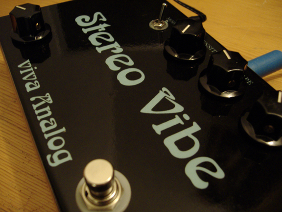
I also did a dual-Univibe one-off called the "The Stereo Vibe" ... Univibe signal path and oscillator, using a V/I converter that drove two sets of 4 matched opto-couplers ... finding 8 matched (high sensitivity) NSL-32-SR3 opto-couplers was a real challenge // possibly the "deepest" sounding unit yet ... where cell resistance spans 10 Meg down to 100 ohms ... whereas in a bulb-based Univibe the cells might see a 1k to 1 Meg range at max intensity (with good cells, and when well set up ...)
http://www.lynx.net/~jc/vivaAnalogStereoVibe.mp3
I've got some good bass samples somewhere ... very interesting at times
some I made with the SV45 and recently with the StereoPhaze I did last winter ...
whenI get a chance I'll post StereoPhaze samples, although it doesn't go deep like the opto-ones
PWM has serious limits placed upon it ... and you can hear ticking when at the end of the sine-sweeps
otherwise, it's way more balanced than any of the other ones I built ...
PWM side-to-side matching is automatically accurate ... as clock inversion gives use inverted pulse-width
but with optical units perfect matching and setting-up (bias) will always be a little off ...
part of the reason why I wanted to try stereo samples with the Chora-Tone unit
is that, similar to the PWM Stereo-Phaze, a stereo Chora-Tone unit would also by default provide matched outputs
that is one thing causing strong attraction to Wayne's Chora-Tone design ...
the clip above show what happens when you have perfectly anti-phase LFO's operating
on identical modulators ...
although I'm not expecting this thing to sound like a common (mono) Phase-Shifter
some of the principle apply similarly to Stereo-Vibrato/Phasor circuits ... when used similarly
and so, why we can bring this up up here ...
like I said before, a stereo (anti-phase) version of the Chora-Tone emulator circuit first of all
falls out of the build quite easily ie., without using that much more hardware ...
so, I'm going for a stereo version in each prototype I build ... (while I'm at it, may as well ...)
again, even it if the unit has two outputs it can be used in several ways
as demo'd above ... with only one output for a Dry / Wet mix ... and both outputs for alternative spatiality, etc.
next, I will post some results of the mono-phasor config. for the Chora-Tone ...
I'm not sure we should be comparing typical and atypical phasor circuits to Wayne's "Chorus" ... mainly because the phase shift that occurs in Wayne's circuit doesn't produce a drastic "phase wall" that moves up and down the audio range like we see in phasors ... it seems to me that Wayne's circuit produces a different kind of phase-modulation // an overall more subtle and resulting in a much less "obvious" sounding effect, if i can say that ... more natural, maybe less noticeable ... less clown'ish ... less toy'ish ... (dunno, first impressions ... so far anyway)
in case anybody's interested in having a listen
of course, I didn't invent the (true) stereo Phase concept ... Mutron had the Bi-Phase way before ...
and mine are way simpler in design and function
my first SV unit was based on the Univibe circuitry ... and blindly duplicated the class-A circuits // including the oscillator section it wasn't perfect in terms of side-to-side even-ness ... but it's clear liquid fidelity surpasses what I did later using op-amps ... nice feel // one day would like to re-visit after what I've learnt since
http://www.lynx.bc.ca/~jc/stereoVibe1.html
uses an original triangle-wave to sine-wave converter from an op-amp based LFO (ie., fake sinewave ... bend-able to square) from a triangle wave (op-amp) oscillator ... the phasor stages are opto coupled op-amps stages // each leg like a Phase 45, but with optical resistance ... some guitar clips here:
http://www.lynx.net/~jc/stereoVibe2.html
I also did a dual-Univibe one-off called the "The Stereo Vibe" ... Univibe signal path and oscillator, using a V/I converter that drove two sets of 4 matched opto-couplers ... finding 8 matched (high sensitivity) NSL-32-SR3 opto-couplers was a real challenge // possibly the "deepest" sounding unit yet ... where cell resistance spans 10 Meg down to 100 ohms ... whereas in a bulb-based Univibe the cells might see a 1k to 1 Meg range at max intensity (with good cells, and when well set up ...)
http://www.lynx.net/~jc/vivaAnalogStereoVibe.mp3
I've got some good bass samples somewhere ... very interesting at times
some I made with the SV45 and recently with the StereoPhaze I did last winter ...
whenI get a chance I'll post StereoPhaze samples, although it doesn't go deep like the opto-ones
PWM has serious limits placed upon it ... and you can hear ticking when at the end of the sine-sweeps
otherwise, it's way more balanced than any of the other ones I built ...
PWM side-to-side matching is automatically accurate ... as clock inversion gives use inverted pulse-width
but with optical units perfect matching and setting-up (bias) will always be a little off ...
part of the reason why I wanted to try stereo samples with the Chora-Tone unit
is that, similar to the PWM Stereo-Phaze, a stereo Chora-Tone unit would also by default provide matched outputs
that is one thing causing strong attraction to Wayne's Chora-Tone design ...
the clip above show what happens when you have perfectly anti-phase LFO's operating
on identical modulators ...
although I'm not expecting this thing to sound like a common (mono) Phase-Shifter
some of the principle apply similarly to Stereo-Vibrato/Phasor circuits ... when used similarly
and so, why we can bring this up up here ...
like I said before, a stereo (anti-phase) version of the Chora-Tone emulator circuit first of all
falls out of the build quite easily ie., without using that much more hardware ...
so, I'm going for a stereo version in each prototype I build ... (while I'm at it, may as well ...)
again, even it if the unit has two outputs it can be used in several ways
as demo'd above ... with only one output for a Dry / Wet mix ... and both outputs for alternative spatiality, etc.
next, I will post some results of the mono-phasor config. for the Chora-Tone ...
Last edited by Eb7+9 on Thu Nov 19, 2015 1:04 am, edited 1 time in total.
modern VT circuit analysis and modeling: https://viva-analog.com/product/ifmta-book-pdf/
-
Xplorer
- Senior Member
- Posts: 2471
- Joined: Sun Apr 19, 2009 5:27 pm
- Just the numbers in order: 7
Re: The FM Tube Modulator Jimi Loved
exactly, i hear that instantly compared to a usual phaser, this is what i meant. it sounds a lot more natural than a toy flanger or chorus.the phase shift that occurs in Wayne's circuit doesn't produce a drastic "phase wall" that moves up and down the audio range like we see in phasors ... it seems to me that Wayne's circuit produces a different kind of phase-modulation // an overall more subtle and resulting in a much less "obvious" sounding effect, if i can say that ... more natural, maybe less noticeable ... less clown'ish ... less toy'ish ... (dunno, first impressions ... so far anyway)
Now, the possibilitys to have an anti phase option, and several modulators, it seems to open an infinity of doors !
Dave's feedback complex effect, with the tube modulator included in the chain, is another level, another world. theoricaly, having a compact version could be possible i guess, but as Dave says, it would be hard to manage all the controls alone while playing.
always a pleasure to hear this stereovibe. JC, if you're familiar with the binaural recording technology, it would really fit this vibe, rather than a simple stereo recording, to really "be there" like it sounded for you in the room, with two amps :
with a simple headphone, you can litteraly hear the recorded sound .... on the left, on the right, behind and in front of you !
and illustration here :
https://www.youtube.com/watch?v=Yd5i7TlpzCk
-
Eb7+9
- Senior Member
- Posts: 105
- Joined: Wed Mar 09, 2011 1:30 pm
- Just the numbers in order: 13492
- Contact:
Re: The FM Tube Modulator Jimi Loved
I'm eventually building a full-blown 5-octave prototype ...
and "it" will be what the circuitry I chose to implement with dictates
not too concerned about building a commercial/stage unit at this point
ergonomically, etc ... for the studio, and adventurous performers
in a Chorus pedal, speed and intensity are the two "controls" ...
well, I might have intensity controls on each oscillator
but I'm afraid can't make it a master intensity one // unless we get into opto control, etc ...
and, so far anyway,
we don't have availability of continuous Speed controllers, let alone a single Master speed control
... unless we go the "code" (PIC/PWM) route
so, I'm not sure what kind of "performance" unit this will turn out to be ...
at least I don't think in the usual effect pedal sense
this is gonna be extravangance beyond the usual box
and being more of a subtle structural composition than a "drastic" cut-and-dry effect ...
tweaking some of those inner subtle elements might be really cool in the long run
gotta try to build it to its full potential ... we'll see // that's why all the sims
either way, it will be big and ugly ... and un-wieldy
(LOL)
to recap, the full version will (likely) have ...
now's a good time to put an end to all this simulation non-sense and move onto some kind of build
I'm starting out with the most basic sub-unit // containing almost all the options intended for the full unit
so, with a single modulator ...
no Tank (for now) - providing a wide-band "flat" response ...
and a dry-signal mix circuit ...
being a phase/anti-phase unit it will offer the potential for mono-phasing in each channel ...
so, providing two-anti-phase phasors or vibrato outputs (ie., with 0% dry mix)
with use options as either Mono Vibrato (Chorus) unit, Mono Phasor unit, Stereo Vibrato unit, and Stereo Phasor unit
(the same will go with the big daddy version)
just to give an idea of this "basic" audio example
https://soundcloud.com/eb7-9/baldwin-ch ... let-c-2015
I find it's not too bad at all ... still providing a pleasing (but mild) form of phasing
again, A, B, C feeds haven't been optimized, so who knows how deeper we can make it sound ...!
if I could get a speed control happening on the VCO that would make it much more interesting
(gotta go study that ieee paper ...)
and "it" will be what the circuitry I chose to implement with dictates
not too concerned about building a commercial/stage unit at this point
ergonomically, etc ... for the studio, and adventurous performers
in a Chorus pedal, speed and intensity are the two "controls" ...
well, I might have intensity controls on each oscillator
but I'm afraid can't make it a master intensity one // unless we get into opto control, etc ...
and, so far anyway,
we don't have availability of continuous Speed controllers, let alone a single Master speed control
... unless we go the "code" (PIC/PWM) route
so, I'm not sure what kind of "performance" unit this will turn out to be ...
at least I don't think in the usual effect pedal sense
this is gonna be extravangance beyond the usual box
and being more of a subtle structural composition than a "drastic" cut-and-dry effect ...
tweaking some of those inner subtle elements might be really cool in the long run
gotta try to build it to its full potential ... we'll see // that's why all the sims
either way, it will be big and ugly ... and un-wieldy
(LOL)
to recap, the full version will (likely) have ...
---5 intensity controls ...
5 tank lift switches ...
and five 5-position rotary "rate" switches ...
and a Master volume control ...
and probably a Dry-level control (for producing Phasing in each output - thus option to producing Stereo-Phase besides Stereo-Vibrato)
now's a good time to put an end to all this simulation non-sense and move onto some kind of build
I'm starting out with the most basic sub-unit // containing almost all the options intended for the full unit
so, with a single modulator ...
no Tank (for now) - providing a wide-band "flat" response ...
and a dry-signal mix circuit ...
being a phase/anti-phase unit it will offer the potential for mono-phasing in each channel ...
so, providing two-anti-phase phasors or vibrato outputs (ie., with 0% dry mix)
with use options as either Mono Vibrato (Chorus) unit, Mono Phasor unit, Stereo Vibrato unit, and Stereo Phasor unit
(the same will go with the big daddy version)
just to give an idea of this "basic" audio example
https://soundcloud.com/eb7-9/baldwin-ch ... let-c-2015
I find it's not too bad at all ... still providing a pleasing (but mild) form of phasing
again, A, B, C feeds haven't been optimized, so who knows how deeper we can make it sound ...!
if I could get a speed control happening on the VCO that would make it much more interesting
(gotta go study that ieee paper ...)
Last edited by Eb7+9 on Tue Jan 05, 2016 7:23 am, edited 1 time in total.
modern VT circuit analysis and modeling: https://viva-analog.com/product/ifmta-book-pdf/
-
daveweyer
- Senior Member
- Posts: 713
- Joined: Wed Oct 29, 2014 9:36 pm
- Just the numbers in order: 13492
Re: The FM Tube Modulator Jimi Loved
JC you can get SOME speed control of the Phase shift oscillator by varying the resistors in the RC coupling networks.
In the tube world you could use a transconductance element; a small signal pentode with a gain of 1 has a resistance which is the inverse of the transconductance, i.e. a voltage controlled resistor. (and it's very linear)
An FET or a Mosfet could be configured the same way. All you'd have to work out is how to deal with the DC on the RC networks. LDRs would work too but you'd have to match them, and I don't know what their temperature to resistance characteristics might be.
I'm not sure a continuous LC oscillator frequency change would buy you that much though. It seems to me there are sweet spots for the LF frequencies, and a simple switch between those ranges should pretty well cover the limits of what the device is capable of in a normal musical context.
I've tortured the choratone pretty badly by corrupting the original design, but the sounds I got were too esoteric to be enjoyed by anyone but a handful of musicians who were into sound for sound's sake. The Glass Insects CD sold about 100 copies worldwide--not for everyone quite obviously.
-
Tek465b
- Senior Member
- Posts: 207
- Joined: Sat Jan 10, 2015 9:43 am
- Just the numbers in order: 13492
- Contact:
Re: The FM Tube Modulator Jimi Loved
Switching capacitor to change the oscillator frequency.
If the cap are small value, could you use varicap diode? turning it into a voltage controlled oscillator?, or use pin diode to electronically switch in and out some capacitor? like we do for rf switching.
Or using mixers(frequency mixers) along with one more (variable) local oscillator LO . that will alow changing the frequency of the 3 or 4 fixed oscillator you have in the circuit(if i read correctly) creating intermediate frequencys for each one of them.
Or could the capacitance made variable like they did with the wahwah?.
For the PWM you could use a PWM chip?(tl494 or 555)
I can do arduino programming, dont know if that can be of any help there. I can do pwm, but i have limited range to change the frequency. could probably do it to 1-2hz, but it will require alot more programming.