Page 3 of 6
Re: First 12 series build
Posted: Wed Dec 31, 2014 9:59 pm
by Strat78
Are the F&T directional? Should they be facing the other way for the mains and screens. Not sure about the the power switch wiring either.
Edit: Oh, I forgot you are tapping the 100vac for Japan. So switch is good.

Re: First 12 series build
Posted: Wed Dec 31, 2014 11:04 pm
by Lbrown3743
Alright after looking at a million pictures of other amps i decided to flip the filter caps around and it seems to be working. Ill install the tubes later on tonight.
Re: First 12 series build
Posted: Wed Dec 31, 2014 11:05 pm
by Lbrown3743
I got the power board from ebay a while back. They came that way so i thought is was good. Its a learning experience.
Re: First 12 series build
Posted: Thu Jan 01, 2015 1:23 am
by Strat78
Looks like your good to go now!
Ha ha, I used to blur out Chris' signature on his pt's in my gut shots so I wouldn't offend the powers that be here at metro. Turns out that nobody cares.

Re: First 12 series build
Posted: Thu Jan 01, 2015 6:40 am
by neikeel
I see why you were confused. It is more normal (at least the way Marshall did it) was to have the earth bus of the cap board closest to the pots and switches (the presence pot earth is wired to the screens turret on originals from the first 100w until the caps went up top. (Does not fit with Larry wiring and can cause ground loop hum). The positive of the caps faces the back of the amp. Who did you buy the boards off?
Re: First 12 series build
Posted: Thu Jan 01, 2015 7:02 am
by Lbrown3743
Theres a guy on ebay selling boards. They look awesome but i guess he screwed up this one time. Alright having another problem. Im only getting around 20 vdc on the PI plates. Im getting around 420 where the choke inputs into the 8.2k and 10k Resistors. After the 8.2k im getting around 280vdc. After the 10k im only getting around 28vdc. The resistors are also getting super hot. I changed them once with the same result. Ive been messing with this all day.
Re: First 12 series build
Posted: Thu Jan 01, 2015 8:09 am
by neikeel
Is this without tubes?
Something dragging the voltage down around the droppers/PI. You do not have pics of this bit in your album, have you wired the screens up on the wrong side of the droppers.
There are two ways to arrange the bus wire from the droppers to the PI plates and if you do not know this you can get the feed wire to the screens/choke that comes in one end and the feed to the PI cap which feeds the PI.
Show us a pic and
please tell me you used the correct wire colours and looped the wires up s we can see

Re: First 12 series build
Posted: Thu Jan 01, 2015 8:17 am
by vh junkie
Yes what Neil said about being sure the screens are wired to the choke side of the 8.2k/10k. If its not that, it sounds like something it mis-wired downstream.
If the choke is feeding the 8.2k, then the 10k... the 10k should only be connected to the junction of the 82k/100 that feed the PI (v3); and a 10k that connects to one side of the preamp cap, and feeds the cathode follower (v2); then through another 10k to the other side of the preamp cap, and on to the 100k/100k junction that feeds v1. Makes sure there are no extra connections and that the connection to the tube anodes are wireds right.
Pics might help.
Re: First 12 series build
Posted: Thu Jan 01, 2015 9:02 am
by Lbrown3743
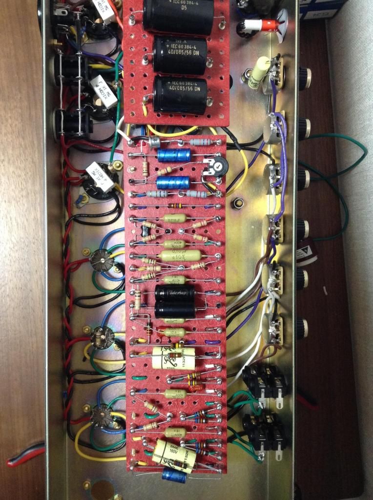
http://i1378.photobucket.com/albums/ah9 ... c925c5.jpg
here is a picture of the current configuration. Ive checked and double checked every 12 series diagram I can find and it looks like everything is hooked up right. And yes this is with out tubes.
Re: First 12 series build
Posted: Thu Jan 01, 2015 9:22 am
by Lbrown3743
the terminal at the bottom left has:
OT primary center tap (white wire)
B+ from the HT fuse (red wire)
and the choke input wire (black wire)
on the top of the board 4th terminal from the left (the drop resistor 8.2k and 10k) has:
choke output (black wire)
1st yellow wire screen caps
2nd yellow screens (pin 6's on V5-V7)
at the other side of the drop resistors the blue wire goes to the PI cap and also to the 2 pre amp caps.
Re: First 12 series build
Posted: Thu Jan 01, 2015 9:27 am
by vh junkie
Is the blue wire hooked to the red dot terminal on the PI cap?
That location should also be attached to the 82k/100k junction AND the 10k that feeds the preamp cap... not directly to the preamp cap, right?
Re: First 12 series build
Posted: Thu Jan 01, 2015 9:32 am
by vanhalen5150
Coming along nice.

Re: First 12 series build
Posted: Thu Jan 01, 2015 9:39 am
by Lbrown3743
Yes the blue wire is connected to the PI cap. Then also feeds to the pre amp caps via a bus wire under the board through a 10k. The blue wire goes from the PI cap to the 8.2 and 10k junction thats leads to the PI plate resistors via a bus wire under the board. Its how you said it.
Re: First 12 series build
Posted: Thu Jan 01, 2015 9:44 am
by vh junkie
Can you confirm that the blue wire hooked to the red dot terminal on the PI cap?
In one of your pics it looks backwards...
Re: First 12 series build
Posted: Thu Jan 01, 2015 9:34 pm
by Lbrown3743
got everything working. Made a short clip before I have to run. Fine tuning to begin later.
https://soundcloud.com/lbrown3743/my-song-3