Ok that makes it tricky!
I would not extend the wires if you do not have to. If they will not reach the way we discussed then I would go back to your sketch above. That will be like a 50w although you will need to plan your harness to allow for the filter can wiring to avoid is tlooking like a rats nest of wires.
upcoming 1969 SL build: PT orientation, wire dress?
-
neikeel

- Senior Member
- Posts: 7231
- Joined: Tue Dec 06, 2005 8:31 am
- Location: Suffolk, England
-
young flower
- Senior Member
- Posts: 119
- Joined: Sun Mar 04, 2012 7:38 pm
- Just the numbers in order: 13492
- Location: Austria, Vienna
Re: upcoming 1969 SL build: PT orientation, wire dress?
And what about bringing the heaters directly down to V7 between mains and screens filter caps and tranny? Wouldn´t that work too? Why not extend them?
Cheers Karim
Cheers Karim
-
neikeel
- Senior Member
- Posts: 7231
- Joined: Tue Dec 06, 2005 8:31 am
- Location: Suffolk, England
Re: upcoming 1969 SL build: PT orientation, wire dress?
You can extend them but in general I would avoid it (you need excellent soldering, physically twist the wires together and use good insulation/shrink wrap.
Ideally make sure the wires are routed directly back to the back of the chassis from the PT and along the far edge of the chassis tucked away before coming down to V7.
Ideally make sure the wires are routed directly back to the back of the chassis from the PT and along the far edge of the chassis tucked away before coming down to V7.
Neil
-
young flower
- Senior Member
- Posts: 119
- Joined: Sun Mar 04, 2012 7:38 pm
- Just the numbers in order: 13492
- Location: Austria, Vienna
Re: upcoming 1969 SL build: PT orientation, wire dress?
I understand. But if you look at the sketch I posted earlier, which you recommended to me to use instead of extending the heaters:
So - I guess, it doesn´t make that much of a difference if it is the heaters or the high voltage taps+primaries running that way.
So, I guess I could as well turn the tranny and route the heaters that way i.e. directly down to V7 between tranny and filter caps (but as close to the tranny as possible).
If I do the wiring that way, the high voltage taps and primaries will run between the tranny and filter caps, exactly where the heaters would run if I bring them directly down to V7 (with the tranny installed the other way round).I would not extend the wires if you do not have to. If they will not reach the way we discussed then I would go back to your sketch above.
So - I guess, it doesn´t make that much of a difference if it is the heaters or the high voltage taps+primaries running that way.
So, I guess I could as well turn the tranny and route the heaters that way i.e. directly down to V7 between tranny and filter caps (but as close to the tranny as possible).
-
neikeel
- Senior Member
- Posts: 7231
- Joined: Tue Dec 06, 2005 8:31 am
- Location: Suffolk, England
Re: upcoming 1969 SL build: PT orientation, wire dress?
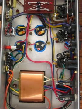
The amp in the pics and your diagram has the heaters making a loop around V7 - try to avoid that.
Here is one of mine - before I have bundled and straightened the looms:
http://i76.photobucket.com/albums/j2/ne ... 1127-1.jpg
Here is one of mine - before I have bundled and straightened the looms:
http://i76.photobucket.com/albums/j2/ne ... 1127-1.jpg
Neil
-
young flower
- Senior Member
- Posts: 119
- Joined: Sun Mar 04, 2012 7:38 pm
- Just the numbers in order: 13492
- Location: Austria, Vienna
Re: upcoming 1969 SL build: PT orientation, wire dress?
Oke Neil - much obliged.
Made another sketch....
This is with the PT rotated 180° - in other words: heater exits on tranny facing power/stdby switch.
There will be no loops around the tube - will split the wires very close to V7, so that´s not drawn too well. primaries will be twisted too of course.

Made another sketch....
This is with the PT rotated 180° - in other words: heater exits on tranny facing power/stdby switch.
There will be no loops around the tube - will split the wires very close to V7, so that´s not drawn too well. primaries will be twisted too of course.
-
julkke
- Senior Member
- Posts: 675
- Joined: Mon Mar 19, 2012 1:07 pm
- Just the numbers in order: 13492
- Location: Finland
-
young flower
- Senior Member
- Posts: 119
- Joined: Sun Mar 04, 2012 7:38 pm
- Just the numbers in order: 13492
- Location: Austria, Vienna
Re: upcoming 1969 SL build: PT orientation, wire dress?
Thanks for the feedback  !
!
I think this is the way I´m gonna do it. Of all the options this looks best to me. I need to get some lacing chord: I´ll twist the heaters+heater CT and 6,3 V lamp wires separately, then lace them together tightly and keep them close to the tranny when routed to the back. Primaries twisted and along the edge of the chassis to the voltage selector. Sounds like a plan me thinks .
.
I opened another thread concerning dual voltage switching - I´d really appreciate it if somebody could give me a few hints over there.
Thanks
YF
I think this is the way I´m gonna do it. Of all the options this looks best to me. I need to get some lacing chord: I´ll twist the heaters+heater CT and 6,3 V lamp wires separately, then lace them together tightly and keep them close to the tranny when routed to the back. Primaries twisted and along the edge of the chassis to the voltage selector. Sounds like a plan me thinks
I opened another thread concerning dual voltage switching - I´d really appreciate it if somebody could give me a few hints over there.
Thanks
YF
-
neikeel
- Senior Member
- Posts: 7231
- Joined: Tue Dec 06, 2005 8:31 am
- Location: Suffolk, England
Re: upcoming 1969 SL build: PT orientation, wire dress?
No.
You have the feed to V7 from below and you will be taking the supply to V6 from above creating an ac loop around V7. - to be avoided. I know you see it on some builds (even Georges 45 instructions but in principle it is bad practise!).
To spend lots of time preparing optimum grounding (Larry or SDM etc) and then set it like that is incorrect. If you are going to mount the PT like that take the wires round and extend them.
Neil
-
young flower
- Senior Member
- Posts: 119
- Joined: Sun Mar 04, 2012 7:38 pm
- Just the numbers in order: 13492
- Location: Austria, Vienna
Re: upcoming 1969 SL build: PT orientation, wire dress?
Hmm. This is really more complicated than I thought.
So - generally speaking: it´s important that all the AC wires to V7 approach from the same side, including the lamp wires?
Oke - in this case I won´t do it like that of course. I think, at this point in time, there is no use in discussing this topic any further. I know the basic rules now, I´ll pick up on the wiring again once I have the chassis and can actually physically fit the PT and components to see the actual wire lengths/ranges.
-
young flower
- Senior Member
- Posts: 119
- Joined: Sun Mar 04, 2012 7:38 pm
- Just the numbers in order: 13492
- Location: Austria, Vienna
Re: upcoming 1969 SL build: PT orientation, wire dress?
Well - I somehow grew fond of these sketches, so I couldn´t resist and made another one:

This is the way the wires are routed with the tranny inserted in the "standard" way - i.e. heater exits on tranny facing power tubes.
This is pretty much the same as the picture of the amp I used in my first post:

The only difference being, that in my version the heaters go along the chassis edge and go down to V7 from the edge of the chassis as opposed to the "loops" created when routing the wires from the tranny directly to V7 (like in the picture above). How I´ll actually wire the amp in the end will be decided when I have the chassis.
This is the way the wires are routed with the tranny inserted in the "standard" way - i.e. heater exits on tranny facing power tubes.
This is pretty much the same as the picture of the amp I used in my first post:
The only difference being, that in my version the heaters go along the chassis edge and go down to V7 from the edge of the chassis as opposed to the "loops" created when routing the wires from the tranny directly to V7 (like in the picture above). How I´ll actually wire the amp in the end will be decided when I have the chassis.
-
young flower
- Senior Member
- Posts: 119
- Joined: Sun Mar 04, 2012 7:38 pm
- Just the numbers in order: 13492
- Location: Austria, Vienna
Re: upcoming 1969 SL build: PT orientation, wire dress?
Update: For anybody interested - this is the wiring layout I came up with in the end:
https://dl.dropboxusercontent.com/u/184 ... al.png.png" onclick="window.open(this.href);return false;
I´ll incorporate SDM grounding and a slightly altered power switch layout in my build (see layout for the switch).
There are just two things in this layout that need to be changed:
#1: The primaries will be routed directly up to the voltage selector on the capacitor side of the PT, going to the selector between V6 and V7 to avoid crossing the heaters. I´m doing that because the primary wires on my PT are quite short - so they won´t be long enough to go all the way around the chassis edge and I don´t want to extend them. 50W JMP amps were wired that way: http://amparchives.com/album/Marshall/5 ... 00182.html" onclick="window.open(this.href);return false;
#2: The live wire from the IEC should connect to the tip of the mains fuse holder instead of the sleeve. This makes changing the fuse safer because the fuse you push in with your finger doesn´t contact the live lug (connected to the IEC live) first. The power switch is therefore connected to the sleeve of the mains fuse holder.
-
julkke
- Senior Member
- Posts: 675
- Joined: Mon Mar 19, 2012 1:07 pm
- Just the numbers in order: 13492
- Location: Finland
Re: upcoming 1969 SL build: PT orientation, wire dress?
Looks good, put some heat shrink over mains connections and remember to mount PE securely (thread lock etc.) Just safety freak here I guess, better safe than sorry.
-
young flower
- Senior Member
- Posts: 119
- Joined: Sun Mar 04, 2012 7:38 pm
- Just the numbers in order: 13492
- Location: Austria, Vienna
Re: upcoming 1969 SL build: PT orientation, wire dress?
You mean over the solder joints between primaries and IEC lugs (i.e. over the IEC lugs after soldering)?put some heat shrink over mains connections
I will - thanksemember to mount PE securely (thread lock etc.)
-
julkke
- Senior Member
- Posts: 675
- Joined: Mon Mar 19, 2012 1:07 pm
- Just the numbers in order: 13492
- Location: Finland
Re: upcoming 1969 SL build: PT orientation, wire dress?
young flower wrote:You mean over the solder joints between primaries and IEC lugs (i.e. over the IEC lugs after soldering)?put some heat shrink over mains connections
I will - thanksemember to mount PE securely (thread lock etc.)
Yep, all solder joints on the primary side should have heat shrink on them for safety, heat shrink acts as a strain relief for the wires so they can't break from vibration and go flying around your chassis. Again it's very unlikely to happen but better to do the mains side the safest way.