Page 3 of 5
Re: First post! Getting into amp building. Hot rodded Super
Posted: Sun Dec 09, 2012 6:17 pm
by fretwizard
Re: First post! Getting into amp building. Hot rodded Super
Posted: Sun Dec 09, 2012 6:18 pm
by fretwizard
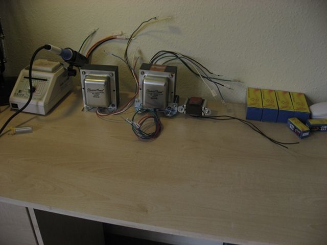
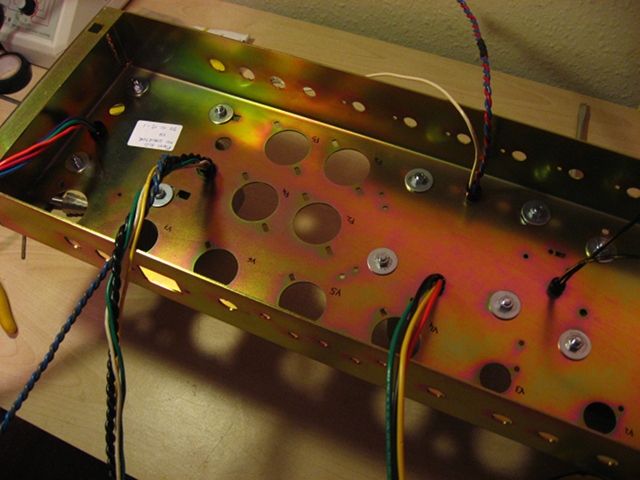
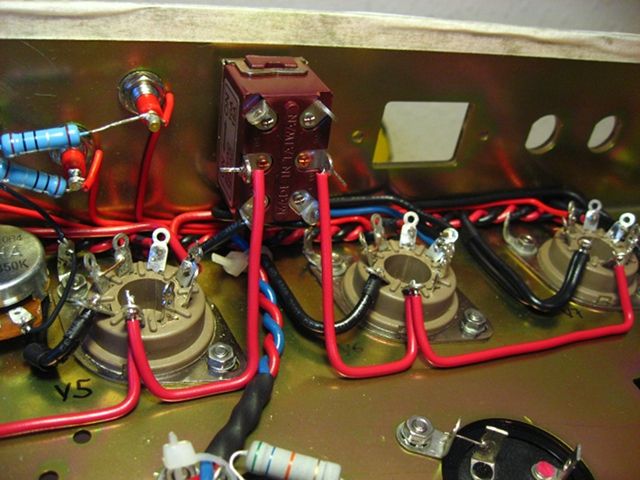
needed to drill new holes for the trannies. Getting them in place was not as easy as I thought.
I figured trannies hardware would not be included so I already had bought 5mm bolts/nuts, with double large washers.
Re: First post! Getting into amp building. Hot rodded Super
Posted: Sun Dec 09, 2012 6:21 pm
by fretwizard
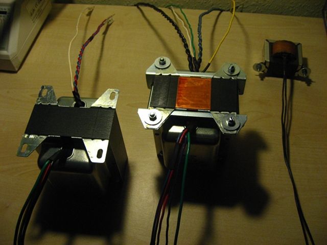
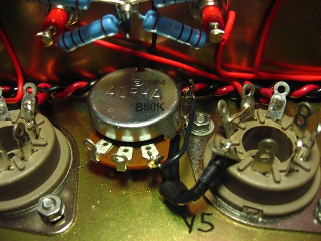
I wanted to leave as less untwisted wire as possible...
Re: First post! Getting into amp building. Hot rodded Super
Posted: Sun Dec 09, 2012 6:22 pm
by fretwizard
Re: First post! Getting into amp building. Hot rodded Super
Posted: Sun Dec 09, 2012 6:25 pm
by fretwizard
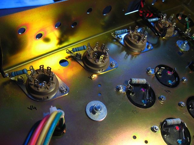
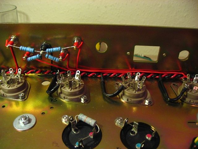
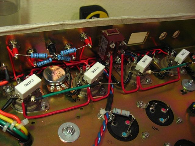
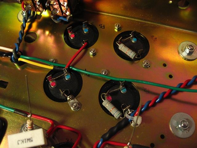
At this point I gave Nik a shout about the bias wiring and half-power switch and he sent me the temporary layout. I realised I had to desolder all the bias resistors and change the position. I was lucky since I had just enough lead to do it clean.
Re: First post! Getting into amp building. Hot rodded Super
Posted: Sun Dec 09, 2012 6:26 pm
by fretwizard
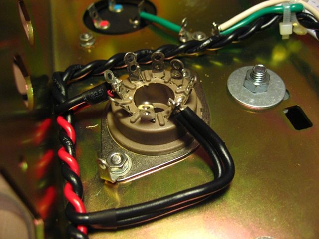
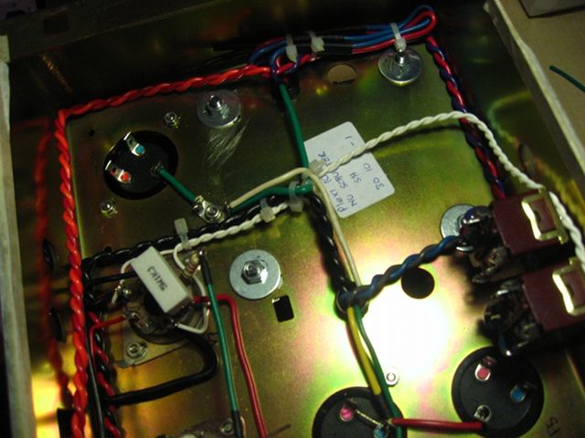
Left 8-Ohm tap unslodered for the NFB wire...
Re: First post! Getting into amp building. Hot rodded Super
Posted: Sun Dec 09, 2012 6:29 pm
by fretwizard
Pentode-Triode Switch
Loads of wires in there...
Re: First post! Getting into amp building. Hot rodded Super
Posted: Sun Dec 09, 2012 6:34 pm
by fretwizard
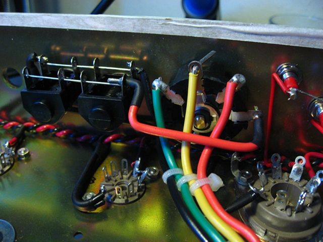
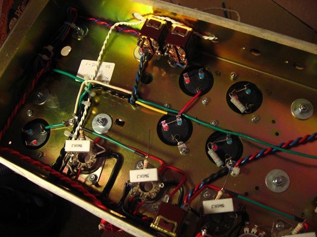
Now this is where I kinda had to stop.
The kit is a bit different compared to the Metro instructions and I wanted to be careful. The manual says I have to connect some wires that will be connected to the turret board, but my board is already wired so I had to check back and forth between manual and ceriatone layout to spot the differences. But I think I'm gonna need Nik's help on this...
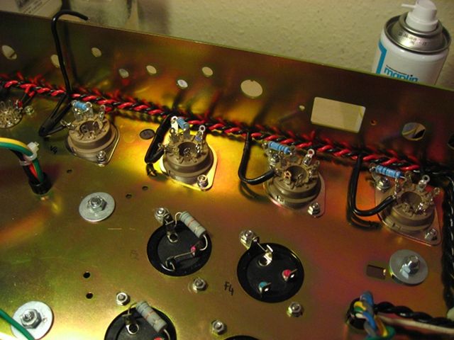
Anyway, I've seen some amp guts pics where the PT primaries are twisted as well so I wanted to do the same between the power switch and the fuse holder. Also the pilot light is wired to the heaters pins on V7.
Re: First post! Getting into amp building. Hot rodded Super
Posted: Sun Dec 09, 2012 8:45 pm
by JimiJames
Outstanding !

Will you be incorporating Larry's grounding scheme ?
Re: First post! Getting into amp building. Hot rodded Super
Posted: Sun Dec 09, 2012 9:26 pm
by fretwizard
JimiJames wrote:Outstanding !
Will you be incorporating Larry's grounding scheme ?
I was thinking about that...

I don't have extra ground lugs for now and I haven't checked which holes I could use on the chassis yet.
Xmas is close and I'll be out of town in a few days so... I was a bit anxious to hear this thing

I was looking at this:
http://forum.metroamp.com/viewtopic.php?f=45&t=31328" onclick="window.open(this.href);return false;
Do you think something is changing with the external bias pot?
Now that I remember, I have some eye-let terminals, but they're for 6mm holes. It could be a temporary solution... if I still have enough wire...
Re: First post! Getting into amp building. Hot rodded Super
Posted: Mon Dec 10, 2012 1:00 am
by julkke
Really neat looking job! Since you want to twist as much as possible twist your ot secondaries too.
Re: First post! Getting into amp building. Hot rodded Super
Posted: Mon Dec 10, 2012 3:55 pm
by Thiez
clean looking build
Re: First post! Getting into amp building. Hot rodded Super
Posted: Mon Dec 10, 2012 6:03 pm
by fretwizard
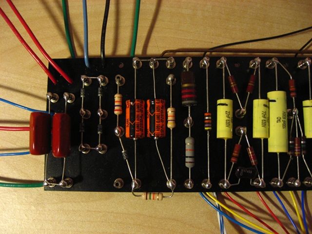
Alright. Nik told me the 'new' layout he gave me was only a reference for wiring the biast test points and the half-power switch.
The rest is just like the layout on ceriatone website:
So now, looking at this thread again:
http://forum.metroamp.com/viewtopic.php?f=45&t=31328" onclick="window.open(this.href);return false;
Can anyone tell me which wires for which point? or at least fill in?
In that picture
at the very bottom I see:
point 1)
- input jacks ch 1
- input jacks ch 2
- V1 cathodes
-
what's the other wire?
point 2)
- normal Vol pot
- bright vol pot
- V2 cathodes
- pre-amp filter cap (which in my case is on the board and already soldered to the ceriatone on-board buss wire)
point 3)
- mids pot
- presence pot
- output jacks. Mine it soldered on the V5 ground lug as per manual.
- F6 filter cap ground? Can anyone tell me the reason?
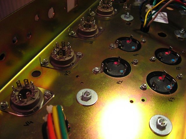
point 4)
- bias pot. Mine is in between the power tubes and it's sharing the ground lug with the bias test points. It would be a mess to deconstruct now...
- Bias 0 from PT. Mine is already cut and soldered to the F6 ground lug with the heaters CT.
Should I really extend the lead and move it here?
- F2 cap ground, I'll have to cut the buss wire and remove the existing lug for this one. just to avoid confusion..
point 5)
- just the bridge rectifier.
Is this all correct?
And can I use the transformers bolts?
Re: First post! Getting into amp building. Hot rodded Super
Posted: Tue Dec 11, 2012 1:10 am
by julkke
The point 1 "other wire" is the heater center tap. It is better not to use transformer bolts for grounding.
Re: First post! Getting into amp building. Hot rodded Super
Posted: Tue Dec 11, 2012 9:34 pm
by Reeltarded
Yeah, get away from the transformer to ground.
It is beautiful. The only thing I would say that I don't like is the heater having the big loop out at every tube. Better to go straight across the tubes there, but hey, that is a great looking build that is over the top on clean work. Good job!