HT very high post rectifier
Posted: Mon Jun 03, 2013 8:24 pm
In the continuing saga of this 100 watt build using a Weber chassis and PT, I have a problem with extremely high DC. It started when I first turned on the standby switch without realizing that I had mistakenly used a 5.6K instead of a 56K as a balance resistor on the screen supply caps. To clarify, I installed one 56K and one 5.6K. It immediately smelled hot and I measured something like 700Vdc one on of the screen caps. I shut if off at once and that's when I noticed my error. Both resistors were burned of course, but it did not blow a fuse. i was out of 56K 2W mo's, so I used 100K's instead as recommended in the Wiki article on bleeder resistors.
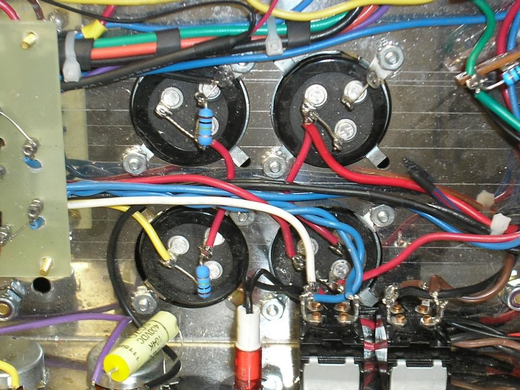
I checked the PT voltages and with 120Vac in using the Variac, which I should have done the first time but didn't, I measured 362Vac on the HT taps. Nothing looks burned or smells like it was burned so I don;t think I damaged anything. I then removed the HT fuse and set the input voltage at 50.2. That is the closest I could get to a round number. I got the following readings which I have noted on the JPEG below.
50.2 volts in was as high as I dared go without going overvoltage on the caps again. Any help would be greatly appreciated. I forgot to mention that I have gone over the wiring three times using the SLP-XL schematic, and everything is correct.
Here is a link to a high-res photo of the work: http://i169.photobucket.com/albums/u217 ... f0a48f.jpg
Thank you everyone
Ivabiggun
I checked the PT voltages and with 120Vac in using the Variac, which I should have done the first time but didn't, I measured 362Vac on the HT taps. Nothing looks burned or smells like it was burned so I don;t think I damaged anything. I then removed the HT fuse and set the input voltage at 50.2. That is the closest I could get to a round number. I got the following readings which I have noted on the JPEG below.
- 100 watt power.jpg (75.72 KiB) Viewed 754 times
Here is a link to a high-res photo of the work: http://i169.photobucket.com/albums/u217 ... f0a48f.jpg
Thank you everyone
Ivabiggun