Alright. Nik told me the 'new' layout he gave me was only a reference for wiring the biast test points and the half-power switch.
The rest is just like the layout on ceriatone website:
So now, looking at this thread again:
http://forum.metroamp.com/viewtopic.php?f=45&t=31328" onclick="window.open(this.href);return false;
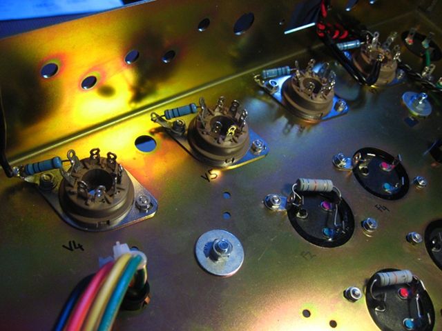
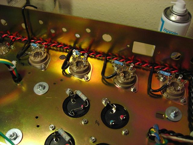
Can anyone tell me which wires for which point? or at least fill in?
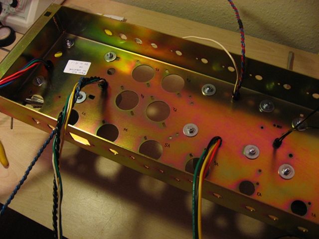
In that picture
at the very bottom I see:
point 1)
- input jacks ch 1
- input jacks ch 2
- V1 cathodes
-
what's the other wire?
point 2)
- normal Vol pot
- bright vol pot
- V2 cathodes
- pre-amp filter cap (which in my case is on the board and already soldered to the ceriatone on-board buss wire)
point 3)
- mids pot
- presence pot
- output jacks. Mine it soldered on the V5 ground lug as per manual.
- F6 filter cap ground? Can anyone tell me the reason?
point 4)
- bias pot. Mine is in between the power tubes and it's sharing the ground lug with the bias test points. It would be a mess to deconstruct now...
- Bias 0 from PT. Mine is already cut and soldered to the F6 ground lug with the heaters CT.
Should I really extend the lead and move it here?
- F2 cap ground, I'll have to cut the buss wire and remove the existing lug for this one. just to avoid confusion..
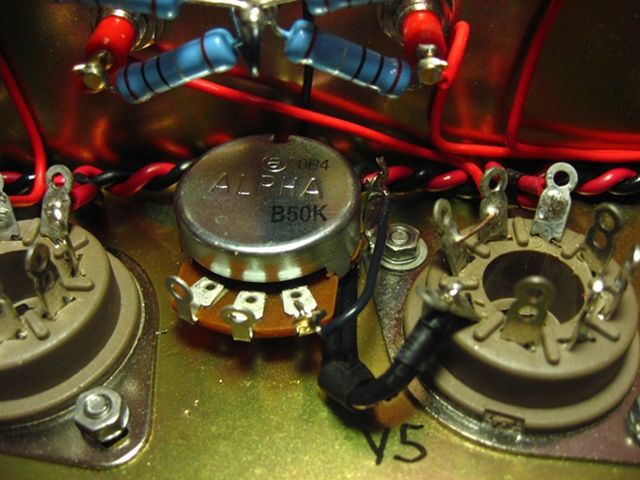
point 5)
- just the bridge rectifier.
Is this all correct?
And can I use the transformers bolts?