S.I.R. 100W SuperLead Schematic pt. II
Moderator: VelvetGeorge
-
CoffeeTones

- Senior Member
- Posts: 1112
- Joined: Mon Oct 11, 2010 9:52 pm
- Just the numbers in order: 7
- Location: USA
Re: S.I.R. 100W SuperLead Schematic pt. II
It's the PI tail resistor. Supposed to better balance the PI. Not connected to the master but to the 470r, PI cathode and 1M grid resistors and then to the .1uF / 4k7 resistor that goes to ground at the presence control. It will make the amp sound different. Good or bad, you decide.
-
bmwfreq

- Senior Member
- Posts: 541
- Joined: Mon Apr 18, 2011 2:43 pm
- Just the numbers in order: 13492
- Location: Northern Utah
- Contact:
Re: S.I.R. 100W SuperLead Schematic pt. II
Thanks, Coffee!CoffeeTones wrote:It's the PI tail resistor. Supposed to better balance the PI. Not connected to the master but to the 470r, PI cathode and 1M grid resistors and then to the .1uF / 4k7 resistor that goes to ground at the presence control. It will make the amp sound different. Good or bad, you decide.
I did bypass the 22k using my resistor substitution box with a 22k resistor (dropping it to around 10+k) and I do think the amp sounds better with the 22k than it does with the stock 10k. So, it was a good change as far as I'm concerned. And if the PI is better balanced, well...two pluses.
Question: I know in the original #34 mod schematic as given by Santiago, it shows the shield cable with the shield connected to pin 1 of V1a. I have found that it sounds closer to the #34 tone if this shield is connected to ground, rather than pin 1 of V1a.
Why is this? Is there a possibility that the shield was connected to ground on the original #34, and Santiago just overlooked this, or just didn't take the time to indicate this when he corrected the schematic that was given to him? Has anyone else experienced this with their #34 mod??
1984 2203 JCM 800
(#34 mod)
1960AV 4x12
2x12 25 watt Greenbacks
2x12 Vintage 30's
[ ..... ]
| O O |
| O O |
(#34 mod)
1960AV 4x12
2x12 25 watt Greenbacks
2x12 Vintage 30's
[ ..... ]
| O O |
| O O |
-
gibsonclassic2001
- Senior Member
- Posts: 328
- Joined: Sat Aug 14, 2010 11:50 am
- Just the numbers in order: 7
Re: S.I.R. 100W SuperLead Schematic pt. II
bmwfreq wrote:Thanks, Coffee!CoffeeTones wrote:It's the PI tail resistor. Supposed to better balance the PI. Not connected to the master but to the 470r, PI cathode and 1M grid resistors and then to the .1uF / 4k7 resistor that goes to ground at the presence control. It will make the amp sound different. Good or bad, you decide.
I did bypass the 22k using my resistor substitution box with a 22k resistor (dropping it to around 10+k) and I do think the amp sounds better with the 22k than it does with the stock 10k. So, it was a good change as far as I'm concerned. And if the PI is better balanced, well...two pluses.
Question: I know in the original #34 mod schematic as given by Santiago, it shows the shield cable with the shield connected to pin 1 of V1a. I have found that it sounds closer to the #34 tone if this shield is connected to ground, rather than pin 1 of V1a.
Why is this? Is there a possibility that the shield was connected to ground on the original #34, and Santiago just overlooked this, or just didn't take the time to indicate this when he corrected the schematic that was given to him? Has anyone else experienced this with their #34 mod??
Connecting the shield to the ground is not cutting heights like the hot shield.
So it should be brighter with the shield to ground.
-
bmwfreq
- Senior Member
- Posts: 541
- Joined: Mon Apr 18, 2011 2:43 pm
- Just the numbers in order: 13492
- Location: Northern Utah
- Contact:
Re: S.I.R. 100W SuperLead Schematic pt. II
Exactly. And the original #34 is extremely bright. So, back to my original question:gibsonclassic2001 wrote:bmwfreq wrote:Thanks, Coffee!CoffeeTones wrote:It's the PI tail resistor. Supposed to better balance the PI. Not connected to the master but to the 470r, PI cathode and 1M grid resistors and then to the .1uF / 4k7 resistor that goes to ground at the presence control. It will make the amp sound different. Good or bad, you decide.
I did bypass the 22k using my resistor substitution box with a 22k resistor (dropping it to around 10+k) and I do think the amp sounds better with the 22k than it does with the stock 10k. So, it was a good change as far as I'm concerned. And if the PI is better balanced, well...two pluses.
Question: I know in the original #34 mod schematic as given by Santiago, it shows the shield cable with the shield connected to pin 1 of V1a. I have found that it sounds closer to the #34 tone if this shield is connected to ground, rather than pin 1 of V1a.
Why is this? Is there a possibility that the shield was connected to ground on the original #34, and Santiago just overlooked this, or just didn't take the time to indicate this when he corrected the schematic that was given to him? Has anyone else experienced this with their #34 mod??
Connecting the shield to the ground is not cutting heights like the hot shield.
So it should be brighter with the shield to ground.
"Is there a possibility that the shield was connected to ground on the original #34, and Santiago just overlooked this, or just didn't take the time to indicate this when he corrected the schematic that was given to him?"
1984 2203 JCM 800
(#34 mod)
1960AV 4x12
2x12 25 watt Greenbacks
2x12 Vintage 30's
[ ..... ]
| O O |
| O O |
(#34 mod)
1960AV 4x12
2x12 25 watt Greenbacks
2x12 Vintage 30's
[ ..... ]
| O O |
| O O |
-
herbvis

- Senior Member
- Posts: 1030
- Joined: Thu Jan 21, 2010 3:58 pm
- Just the numbers in order: 7
Re: S.I.R. 100W SuperLead Schematic pt. II
Frank confirmed the hot shield on #34.
-
herbvis
- Senior Member
- Posts: 1030
- Joined: Thu Jan 21, 2010 3:58 pm
- Just the numbers in order: 7
Re: S.I.R. 100W SuperLead Schematic pt. II
ChrisBurrell wrote:Breaking news guys, just got a email from frank levi, with detailed pictures of the actual #34 mods, he's used the slash AFD100 video to point them out, its pretty much the same as what we've all been doing. e.g.
the .1Uf over 10K V1A
.47Uf over the 820R
680Nf presence cap
150K on the volume.
And something to do with the screen lead from V1, but i can't work it out in the image, this is what frank said.
CHRISTIAN,
THE ATTACHED IS HOT OFF THE PRESS. YOU PROBABLY KNOW MOST OF THIS. I'M WORKING ON THE SCREENED LEAD DETAILS & HOPE TO GET THEM OFF TO YOU SOON. PLEASE BE AWARE THAT, IF YOU DO NOT USED THE SCREENED LEAD, THE CAPACITOR ACROSS THE 100K PLATE RESISTOR CAN BE ANYWHERE FROM 100pF TO 500pF ... DEPENDING ON HOW MUCH & AT WHAT FREQUENCY YOU ARE GETTING FEEDBACK FROM/TO THE GRID LEAD. I WOULD START AT 250pF, IF THAT DOESN'T WORK, 330pF OR 470pF.
CHEERS, FRANK
Unfortuantly i've been asked not to publish anything as it's franks copyright. But if anyone wants the image i can email i guess, not classed as publishing is it?
-
bmwfreq
- Senior Member
- Posts: 541
- Joined: Mon Apr 18, 2011 2:43 pm
- Just the numbers in order: 13492
- Location: Northern Utah
- Contact:
Re: S.I.R. 100W SuperLead Schematic pt. II
Hmmmmmmm. Well; all I can say is, my #34 mod sounds closer to the actual #34 with the shield connected to ground, than it does with the shield connected to pin 1 of V1a. The difference is night and day on my amp.herbvis wrote:Frank confirmed the hot shield on #34.
I'm just saying....
Plus; the AFD100 doesn't have a "Hot-shield". Just something to think about.
-
bmwfreq
- Senior Member
- Posts: 541
- Joined: Mon Apr 18, 2011 2:43 pm
- Just the numbers in order: 13492
- Location: Northern Utah
- Contact:
Re: S.I.R. 100W SuperLead Schematic pt. II
I sent you a PM herb!!herbvis wrote:ChrisBurrell wrote:Breaking news guys, just got a email from frank levi, with detailed pictures of the actual #34 mods, he's used the slash AFD100 video to point them out, its pretty much the same as what we've all been doing. e.g.
the .1Uf over 10K V1A
.47Uf over the 820R
680Nf presence cap
150K on the volume.
And something to do with the screen lead from V1, but i can't work it out in the image, this is what frank said.
CHRISTIAN,
THE ATTACHED IS HOT OFF THE PRESS. YOU PROBABLY KNOW MOST OF THIS. I'M WORKING ON THE SCREENED LEAD DETAILS & HOPE TO GET THEM OFF TO YOU SOON. PLEASE BE AWARE THAT, IF YOU DO NOT USED THE SCREENED LEAD, THE CAPACITOR ACROSS THE 100K PLATE RESISTOR CAN BE ANYWHERE FROM 100pF TO 500pF ... DEPENDING ON HOW MUCH & AT WHAT FREQUENCY YOU ARE GETTING FEEDBACK FROM/TO THE GRID LEAD. I WOULD START AT 250pF, IF THAT DOESN'T WORK, 330pF OR 470pF.
CHEERS, FRANK
Unfortuantly i've been asked not to publish anything as it's franks copyright. But if anyone wants the image i can email i guess, not classed as publishing is it?
1984 2203 JCM 800
(#34 mod)
1960AV 4x12
2x12 25 watt Greenbacks
2x12 Vintage 30's
[ ..... ]
| O O |
| O O |
(#34 mod)
1960AV 4x12
2x12 25 watt Greenbacks
2x12 Vintage 30's
[ ..... ]
| O O |
| O O |
-
budubum92
- Senior Member
- Posts: 249
- Joined: Thu Feb 14, 2013 10:34 am
- Just the numbers in order: 13492
Re: S.I.R. 100W SuperLead Schematic pt. II
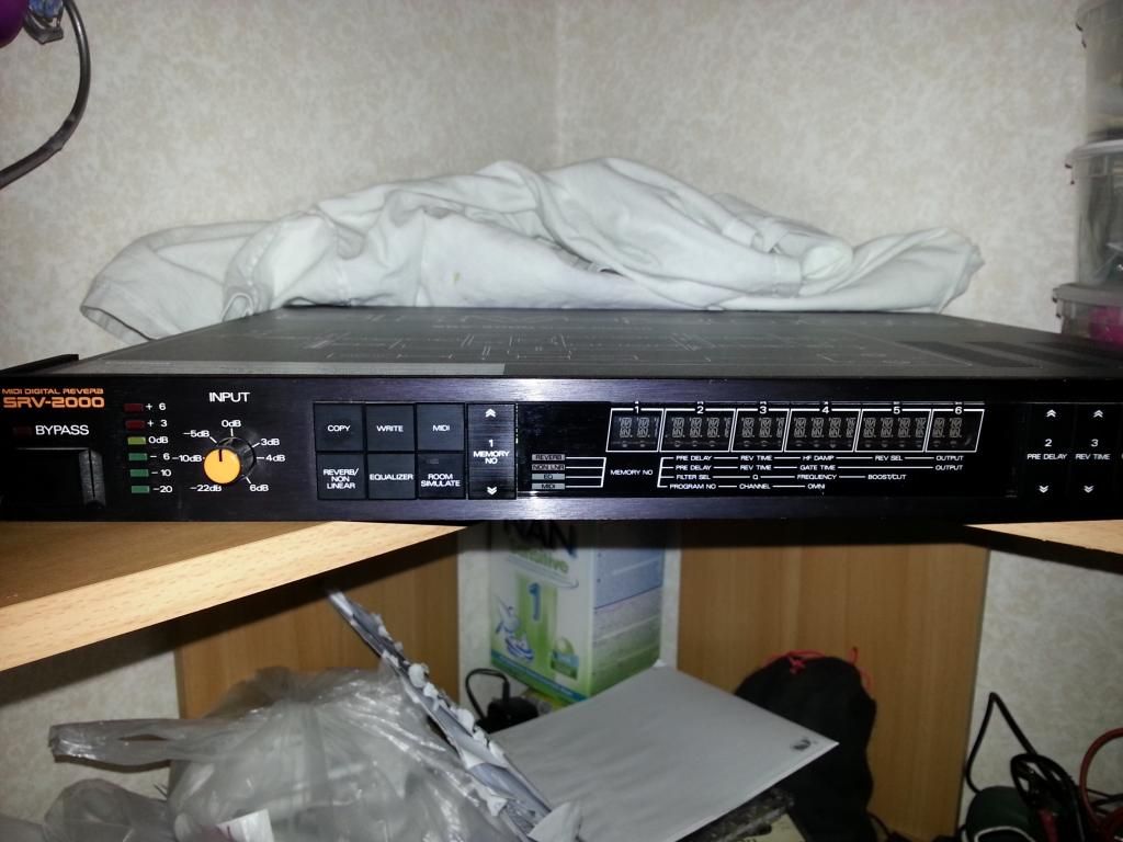
just got myself a Roland SRV 2000

-
budubum92
- Senior Member
- Posts: 249
- Joined: Thu Feb 14, 2013 10:34 am
- Just the numbers in order: 13492
Re: S.I.R. 100W SuperLead Schematic pt. II
...
Last edited by budubum92 on Mon Mar 16, 2015 1:46 am, edited 1 time in total.
-
herbvis
- Senior Member
- Posts: 1030
- Joined: Thu Jan 21, 2010 3:58 pm
- Just the numbers in order: 7
Re: S.I.R. 100W SuperLead Schematic pt. II
Im jelly  Id like to have one of those some day
What were your settings on your last clips?
What were your settings on your last clips?
-
gibsonclassic2001
- Senior Member
- Posts: 328
- Joined: Sat Aug 14, 2010 11:50 am
- Just the numbers in order: 7
Re: S.I.R. 100W SuperLead Schematic pt. II
budubum92 wrote:anyone that can help me on this thread, id really appreciate it. im buying some cables tomorrow but unsure what type. help me here please
http://forum.metroamp.com/viewtopic.php?f=45&t=44194
Hi
Ive used mine in both mixingdesk and in the fx loop.
Fx loop is good enough.
Do a factory reset and set level on rear panel on the mark.
Did you get the user manual?
Its available online.
Btw test the secret delay also. Its great!
-
budubum92
- Senior Member
- Posts: 249
- Joined: Thu Feb 14, 2013 10:34 am
- Just the numbers in order: 13492
Re: S.I.R. 100W SuperLead Schematic pt. II
thanks for replying.gibsonclassic2001 wrote:budubum92 wrote:anyone that can help me on this thread, id really appreciate it. im buying some cables tomorrow but unsure what type. help me here please
http://forum.metroamp.com/viewtopic.php?f=45&t=44194
Hi
Ive used mine in both mixingdesk and in the fx loop.
Fx loop is good enough.
Do a factory reset and set level on rear panel on the mark.
Did you get the user manual?
Its available online.
Btw test the secret delay also. Its great!
i understand ill use a MONO cable between my mic-preamp and SRV2000 input but what type of cable should i use on the outputs A and B? still MONO cables, stereo TRS cabe or what?
i want to use SRV2000 between my mic preamp and PC`s mic input.
-
rockgod212
- Senior Member
- Posts: 1178
- Joined: Wed Mar 03, 2010 11:47 pm
- Just the numbers in order: 7
- Location: U.S.A.
- Contact:
Re: S.I.R. 100W SuperLead Schematic pt. II
without knowing what hardware/ software DAW system you are using, its hard to say. normally those effects are used as outboard gear with your DAW's fx loop, if it has one that is.
budubum92 wrote:thanks for replying.gibsonclassic2001 wrote:budubum92 wrote:anyone that can help me on this thread, id really appreciate it. im buying some cables tomorrow but unsure what type. help me here please
http://forum.metroamp.com/viewtopic.php?f=45&t=44194
Hi
Ive used mine in both mixingdesk and in the fx loop.
Fx loop is good enough.
Do a factory reset and set level on rear panel on the mark.
Did you get the user manual?
Its available online.
Btw test the secret delay also. Its great!
i understand ill use a MONO cable between my mic-preamp and SRV2000 input but what type of cable should i use on the outputs A and B? still MONO cables, stereo TRS cabe or what?
i want to use SRV2000 between my mic preamp and PC`s mic input.
"purple power rules"
-
budubum92
- Senior Member
- Posts: 249
- Joined: Thu Feb 14, 2013 10:34 am
- Just the numbers in order: 13492
Re: S.I.R. 100W SuperLead Schematic pt. II
...
Last edited by budubum92 on Mon Mar 16, 2015 1:46 am, edited 1 time in total.