glad to be able to write this post, hope y'all enjoying following this project development ...
to recap,
one thing that mystified me about Gilbert's Translinear circuit of Fig. 3 (Loizos) was how the ring is coupled together later ... so, I contacted one of the authors and he recommended using capacitive level shifting after I told him about the approach I was taking ... anyhow, caps wouldn't work at our low speeds // unless we use stupidly large caps ... so, scratch that ...
besides, Gilbert's paper clearly shows a loop of those two Translinear blocks
DC coupled to each other
I figured, that's the only way that ring could work for us (at super low speeds)
the author also suggested NOT using that module, period ...
even tho the text makes it sound like a viable engine to work with // ... that's how I read it anyway
I found this all a bit confusing
then, I noticed Gilbert's patent in the ref section
which encouraged me to SPICE the "bad-boy" module on its own a bit ...
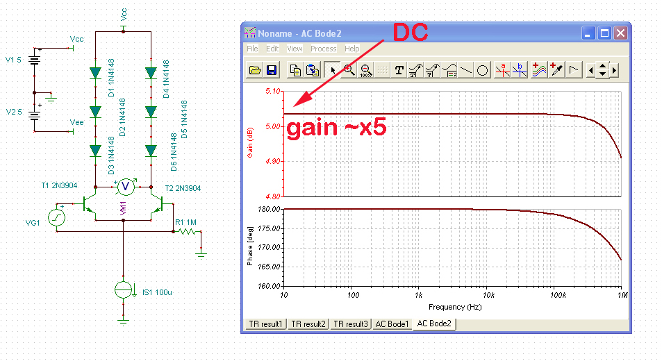
http://www.lynx.net/~jc/translinearGm-R ... n100nA.jpg
using TINA-TI component models, we get a differential small-signal voltage gain of about 5v/v at DC ...
(the paper claims 3v/v, guessing because they might have used diode connected transistors in their case)
to compare, the op-amp version of the oscillator (shown way above) has a gain of x2 per stage ...
and no loading between stages ...
in case this is not clear to some,
the circuit, and therefore the whole oscillator, operates in a differential manner, as opposed to single ended referenced to GND ... voltages on one side go up while their counterpart on the opposite leg go down, and vice versa for currents ...
it turns out that the place where the level shifter takes its signal can also be the place where the output current converter can take its signal from
Also, notice that we 're working with device models for common "hobby-DIY" parts, the ones I'll be using myself ...
1n4148 Si diodes, 2n3906 PNP and 2n3904 NPN Si transistors
the idea is to approximate as closely as possible the same circuit we will be bread-boarding and building later ...
for those interested, it then gives us a chance to compare simulation results to their real-world equivalent ...
to see how full-of-sh*t the simulator was all along, or not ... but I digress ...
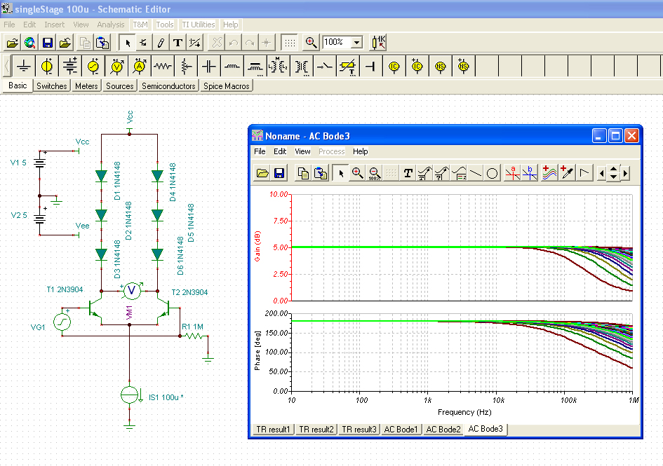
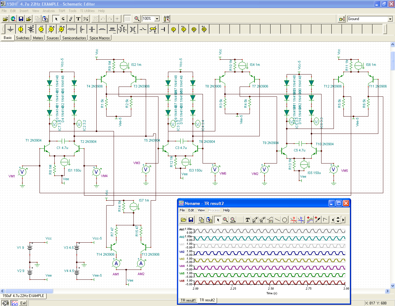
now, if the bias current is stepped from 1uA to 120uA, voltage gain is maintained (except for frequency response) :
http://www.lynx.net/~jc/translinearGm-Rstage1-120uA.jpg
it confirms the theory presented in the paper ... namely that the differential voltage gain
does not vary with bias current ... ie., Gm changes inversely to diodes resistances, and at the same rate
to understand how this is relevant to our oscillator goals here ...
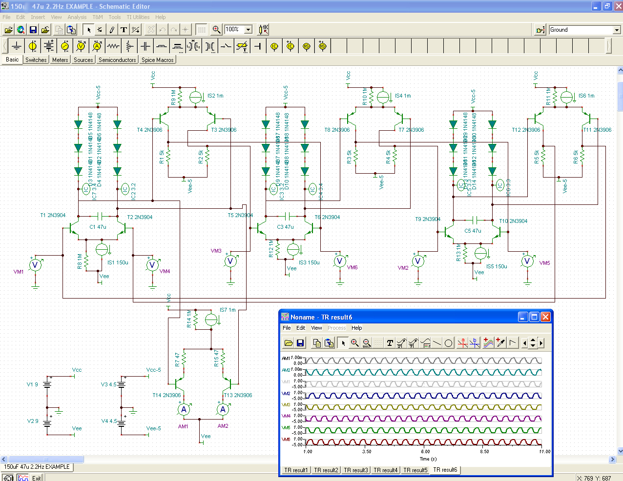
when we stick a capacitor across there you get a RC time constant that varies directly with current
since the voltage gain stays the same, the loop gain will not vary but the internal time constants will ...
we get a variable frequency oscillator
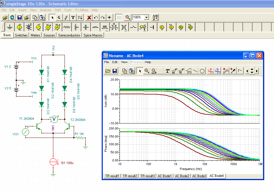
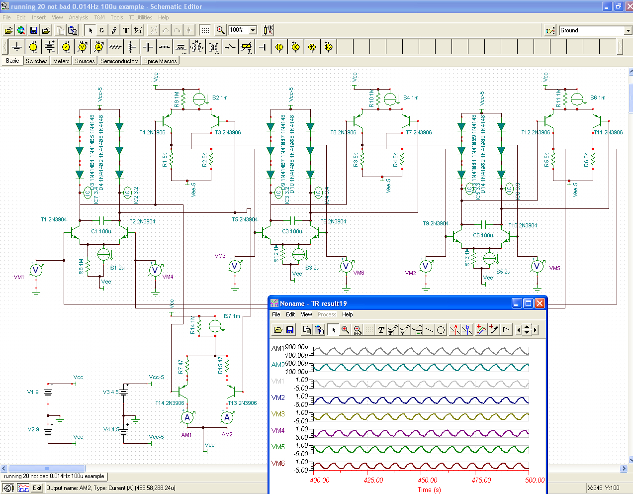
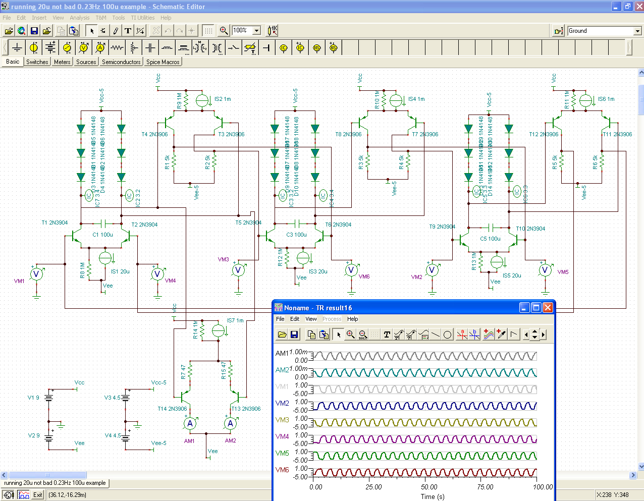
I found that the gain stage preserves this constant-gain property down to about 20nA ... which is pretty darn good
seen here with bias current swept from 10nA to 120nA (ie., 0.01uA to 0.12uA) :
http://www.lynx.net/~jc/translinearGm-R ... -120nA.jpg
this gives us an idea of the usable bias range (minima)
now, if we tie these guys together in a loop ... Bases to Collectors ... then, for one, a stable DC
operating point cannot be achieved ... and this makes the circuit quite a bit more difficult to analyze IMO
and, for the life of me could not figure out if that was part of the idea
so, to answer that I inserted a differential level-shifting stage ... one with gain built in
... this effectively removes the ambiguity //
and, possibly what the authors meant by THIS circuit requiring high supply headroom
I sim'ed many combinations, some with 2 or 1 diodes ... but went back to the three diode case
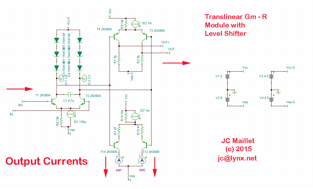
so, the basic Gilbert Translinear Gm-R module gets augmented to this :
http://www.lynx.net/~jc/translinearGm-R ... 015JCM.jpg
the horizontal arrows show the In/Out flow of differential voltages in the ring
while the down arrows show the current outputs that will be used to drive the bias input of OTA's ...
three of these are tied together in a (DC coupled) ring according to the diagram in Fig. 1 of Loizos' paper
and looks like this :
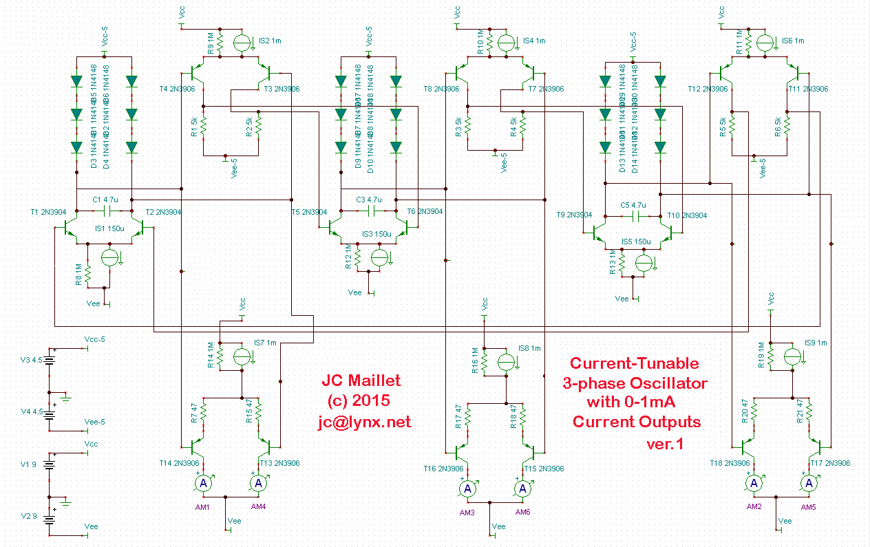
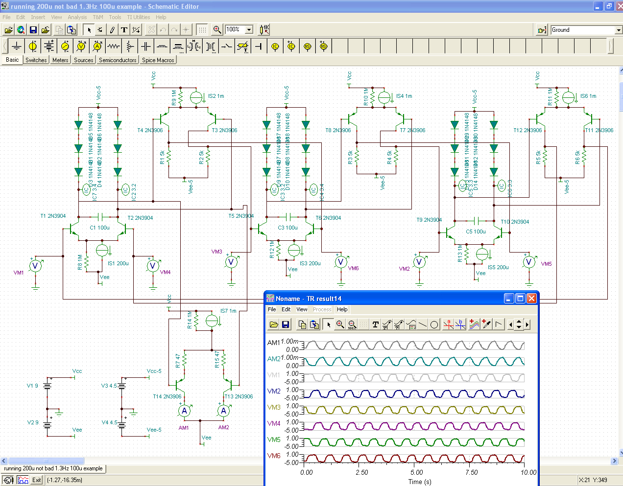
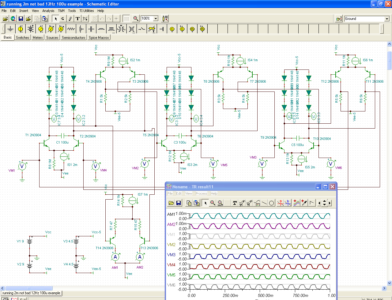
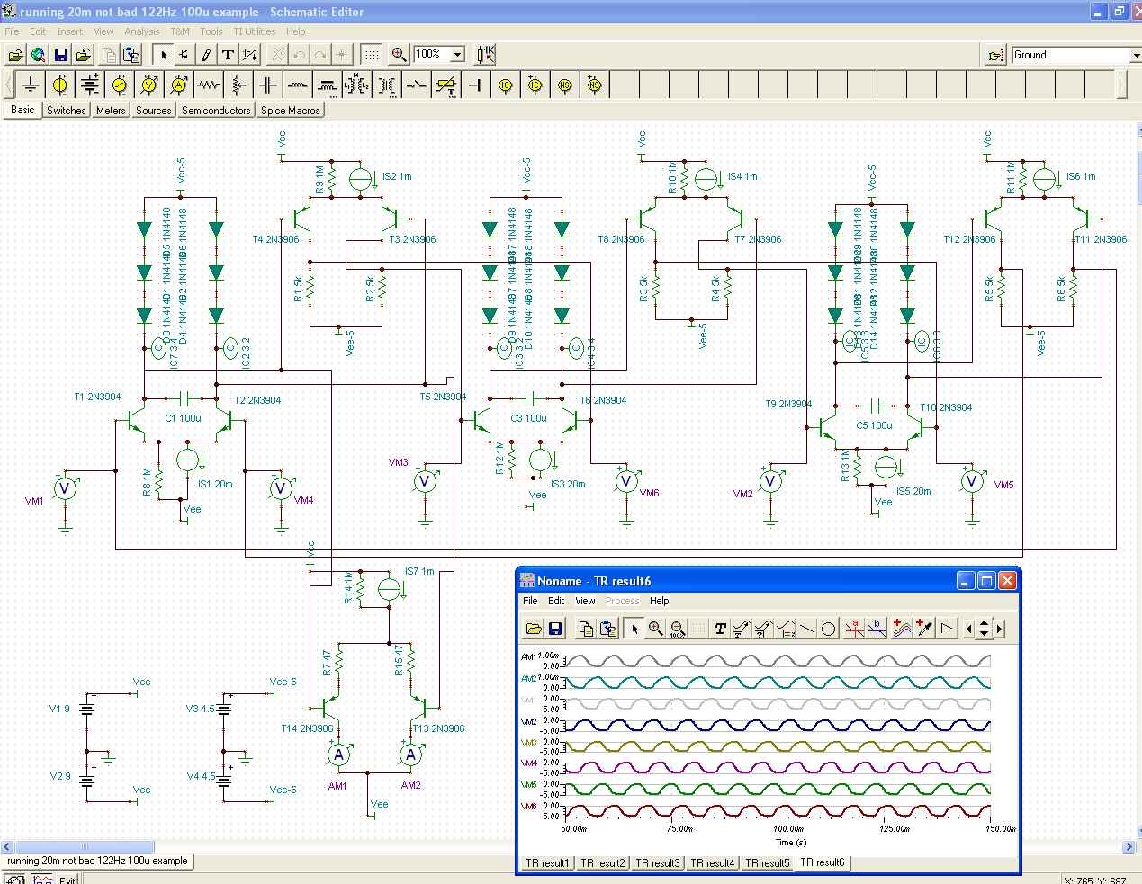
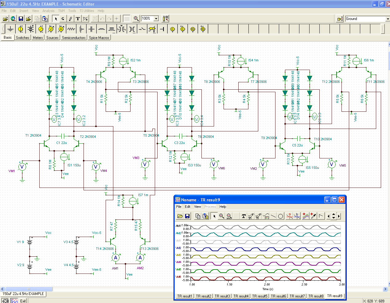
http://www.lynx.net/~jc/CC-3phase-Osc-2015JCM.jpg
there are now three currents (IS1, IS3, and IS5) that control the oscillation RATE
these can be operated from a single MASTER current echo'd thru matched or scaled current mirrors
aside from it's overall straightforward design, it does
require at least 9 matched device pairs of NPN and PNP devices
which is not such a difficult thing to do with BJT's ...
http://users.ece.gatech.edu/mleach/lowtim/part2.html
in all the total number of transistors making up a complete oscillator block (incl. sources) would be 27
the bias current in the shifter stages is set arbitrarily to 1mA
and the same for the Output current converters (OTA's blow at 2mA, so anything below that would be ok)...
choosing 1mA makes it easy to read the data afterwards, and help see if the diff-pairs are being swung wide enough, etc ...
we make note of the order of positions in the circuit for the output currents ...
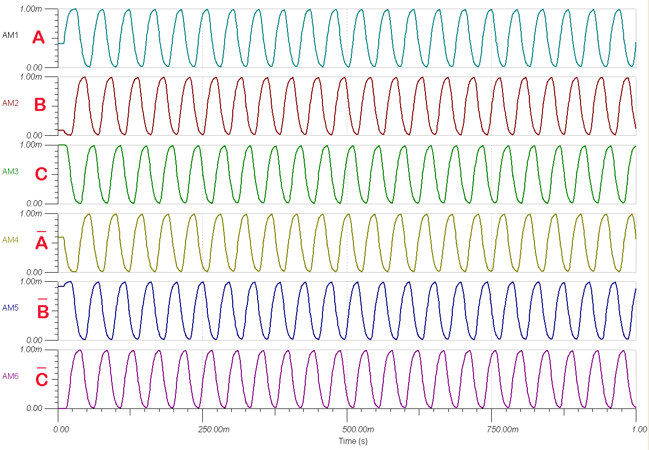
and here are the final current output wave-forms:
http://www.lynx.net/~jc/CC-3phase-OscOu ... 015JCM.jpg
I think the 120 degree difference between waves is easy to see here (answering your question Dave ...)
and, this aplies to both in-phase and anti-phase groups // making synchronous stereo'izing of the effect possible
(something Wayne himself might have dug ...!) ...notice also the full 0 to 1mA output current range being spanned
I'll admit, part of my problem in all this was assuming that the Translinear circuit was going to be responsible for giving me a sine-shape to the wave-forms ... a realize my foolishness now, and that in fact, it makes perfect sense to see the wave-forms looking like they do ... possibly as they look in your Chora-Tone unit
I'm very pleased with the solution discovered ... !!
27 transistors and 18 diodes per oscillator is as good to hope for in a discrete analog solution exhibiting this kind of control
I can even see this circuit having wider application elsewhere, maybe in an e-bike ...(*!*)
... more on the circuit's performance shortly
~jcm


