So I am converting a POS Bugera to a JCM800 2203. Everything is wired up but I am having a VERY strange problem figuring out the heater voltages. The power transformer is a stock Bugera job and I am only using the HT and Heater taps. There is no center tap on either the HT or Heater tap.
I get 123VAC on the primaries. I get 490VAC on the HT secondaries and 6.9VAC on the Heater secondaries.
But when I wire the Heaters to the tube sockets, I get 95-100VAC on each side of the tube socket.
What the heck is going on?
Weird Heater Supply Problem - And other solutions!
Moderator: VelvetGeorge
-
marshallnoise
- Senior Member
- Posts: 169
- Joined: Wed Jun 10, 2015 1:58 pm
- Just the numbers in order: 13492
- Location: Oceanslime, CA
Weird Heater Supply Problem - And other solutions!
Last edited by marshallnoise on Mon Sep 18, 2017 8:18 pm, edited 1 time in total.
-
snakepit86

- Senior Member
- Posts: 156
- Joined: Wed Feb 27, 2008 8:55 pm
Re: Weird Heater Supply Problem - 95VAC? WTF?
did track down the traces on the power tubes pcbs?
-
marshallnoise
- Senior Member
- Posts: 169
- Joined: Wed Jun 10, 2015 1:58 pm
- Just the numbers in order: 13492
- Location: Oceanslime, CA
Re: Weird Heater Supply Problem - 95VAC? WTF?
Here is the 1990 schematic, but I am not sure what difference the old circuit boards traces went to matters as I started fresh with just a chassis, PT and OT.
I think they made an artificial center tap with the two 100 ohm resistors going to ground through a cap.
Might this be an issue?
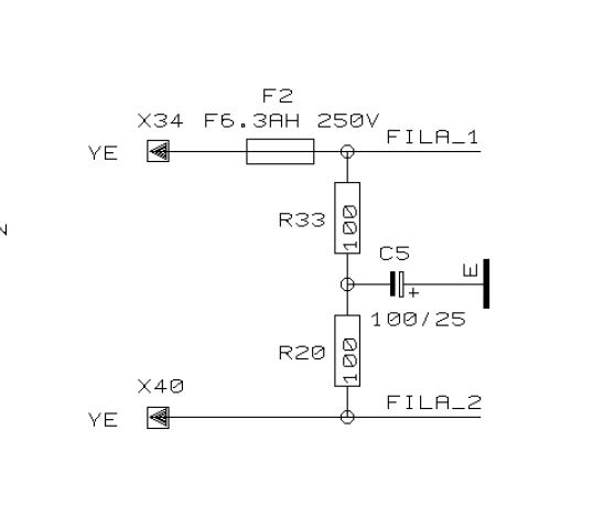 Bugera 1990 Filament by Paul Abbott, on Flickr
I think they made an artificial center tap with the two 100 ohm resistors going to ground through a cap.
Might this be an issue?
Bugera 1990 Filament by Paul Abbott, on Flickr-
neikeel

- Senior Member
- Posts: 7231
- Joined: Tue Dec 06, 2005 8:31 am
- Location: Suffolk, England
Re: Weird Heater Supply Problem - 95VAC? WTF?
The artificial heater centre tap with the 100R resistors is there largely to minimise hum.
Sometimes you also need to ground one end of the heater chain for ground reference.
I see the circuit has a separate heater fuse so if I am wrong you have some protection!
Sometimes you also need to ground one end of the heater chain for ground reference.
I see the circuit has a separate heater fuse so if I am wrong you have some protection!
Neil
-
marshallnoise
- Senior Member
- Posts: 169
- Joined: Wed Jun 10, 2015 1:58 pm
- Just the numbers in order: 13492
- Location: Oceanslime, CA
Re: Weird Heater Supply Problem - 95VAC? WTF?
Hey Neil!
So to close this mystery, when I created the artificial center tap, I was able to get 3.4VAC on each leg. Go freaking figure.
Oddly, I am having a similar problem using a full wave bridge rectifier for this PT that has no HT center tap. Actually, I get 538VCD after rectification with the FWBR coming out of the top of the BR. So that's good.
But I am trying to get some negative VDC to the bias supply. But I suppose that is another issue.
Paul
-
neikeel
- Senior Member
- Posts: 7231
- Joined: Tue Dec 06, 2005 8:31 am
- Location: Suffolk, England
Re: Weird Heater Supply Problem - 95VAC? WTF?
If no bias tap then you will need to take an ac feed off the PT before the rectifier (like the 50w Marshalls and the JTM45/100).
Single wire to the dropping resistor and diode works but you will need to play with the dropper resistor to get into range. I would try 150k and see what you get.
Single wire to the dropping resistor and diode works but you will need to play with the dropper resistor to get into range. I would try 150k and see what you get.
Neil
-
marshallnoise
- Senior Member
- Posts: 169
- Joined: Wed Jun 10, 2015 1:58 pm
- Just the numbers in order: 13492
- Location: Oceanslime, CA
Re: Weird Heater Supply Problem - 95VAC? WTF?
Thanks! I got that cured and I am now getting the right negative voltages. Thanks! 
Still troubleshooting.
Still troubleshooting.
-
Littlewyan
- Senior Member
- Posts: 200
- Joined: Fri Dec 06, 2013 9:27 am
- Just the numbers in order: 13492
- Location: United Kingdom
Re: Weird Heater Supply Problem - 95VAC? WTF?
Because you have no centre tap on the HT you will need to use a Capacitor Coupled Bias Supply.
http://valvewizard.co.uk/bias.html
Merlin explains it here. It's an odd circuit and you will have to wire up the standby switch a bit differently for it to work properly when the amp is in standby. Also for safety reasons you may want to use a special capacitor. One that is rated for high AC Voltage and I think it shorts when it fails or something? I bought a few. Marshall have used this circuit a few times and I used it in my last build. I can give further details in a few days time if you need them .
.
Where have you currently got your standby switch? After the first filter cap?
http://valvewizard.co.uk/bias.html
Merlin explains it here. It's an odd circuit and you will have to wire up the standby switch a bit differently for it to work properly when the amp is in standby. Also for safety reasons you may want to use a special capacitor. One that is rated for high AC Voltage and I think it shorts when it fails or something? I bought a few. Marshall have used this circuit a few times and I used it in my last build. I can give further details in a few days time if you need them
Where have you currently got your standby switch? After the first filter cap?
-
neikeel
- Senior Member
- Posts: 7231
- Joined: Tue Dec 06, 2005 8:31 am
- Location: Suffolk, England
Re: Weird Heater Supply Problem - 95VAC? WTF?
Sorry I had not appreciated that there is no HT centre tap either. Excellent link to the Valvewizard pageLittlewyan wrote: ↑Thu Sep 14, 2017 7:33 amBecause you have no centre tap on the HT you will need to use a Capacitor Coupled Bias Supply.
http://valvewizard.co.uk/bias.html
Merlin explains it here. It's an odd circuit and you will have to wire up the standby switch a bit differently for it to work properly when the amp is in standby. Also for safety reasons you may want to use a special capacitor. One that is rated for high AC Voltage and I think it shorts when it fails or something? I bought a few. Marshall have used this circuit a few times and I used it in my last build. I can give further details in a few days time if you need them
Where have you currently got your standby switch? After the first filter cap?
Neil
-
Littlewyan
- Senior Member
- Posts: 200
- Joined: Fri Dec 06, 2013 9:27 am
- Just the numbers in order: 13492
- Location: United Kingdom
Re: Weird Heater Supply Problem - 95VAC? WTF?
Haha it's cool. I went through all of this with my last build so I'm going to try and save this guy a lot of pain.
-
marshallnoise
- Senior Member
- Posts: 169
- Joined: Wed Jun 10, 2015 1:58 pm
- Just the numbers in order: 13492
- Location: Oceanslime, CA
Re: Weird Heater Supply Problem - 95VAC? WTF?
Yes! This is exactly what I used. But I don't like the fact that the way my standby switch is wired, I don't get any bias until I turn the standby switch to operate mode. The HT is going into the standby switch, then when the switch is flipped, it goes to the rectifier. Then the bias supply gets the voltage it needs.Littlewyan wrote: ↑Thu Sep 14, 2017 7:33 amBecause you have no centre tap on the HT you will need to use a Capacitor Coupled Bias Supply.
http://valvewizard.co.uk/bias.html
Merlin explains it here. It's an odd circuit and you will have to wire up the standby switch a bit differently for it to work properly when the amp is in standby. Also for safety reasons you may want to use a special capacitor. One that is rated for high AC Voltage and I think it shorts when it fails or something? I bought a few. Marshall have used this circuit a few times and I used it in my last build. I can give further details in a few days time if you need them
Where have you currently got your standby switch? After the first filter cap?
I have a 20-0-20 tap off my transformer that is unused. I was thinking I could use a half wave rectifier for it, but the most DC I could get out of it is 40vdc, right? If I used a bridge rectifier then I could get 1.4 x 40vac and that would be 56dc after rectification.
If I did that, would the positive lead go to ground and the negative lead go to the bias circuit? Center tap to ground, right?
I am very much a noob. And I discovered that leaky coupling capacitors can cause runaway bias problems!
-
Littlewyan
- Senior Member
- Posts: 200
- Joined: Fri Dec 06, 2013 9:27 am
- Just the numbers in order: 13492
- Location: United Kingdom
Re: Weird Heater Supply Problem - 95VAC? WTF?
No need to wire up a different circuit, we just need to sort the standby switch. So at the moment is the switch switching both AC inputs to the rectifier or just one?
-
marshallnoise
- Senior Member
- Posts: 169
- Joined: Wed Jun 10, 2015 1:58 pm
- Just the numbers in order: 13492
- Location: Oceanslime, CA
Re: Weird Heater Supply Problem - 95VAC? WTF?
Cool! Both are going to the standby switch.
Edit, more info:
The switches are DPDT and the power switch is lighted. Wiring the power switch was easy.
Edit, more info:
The switches are DPDT and the power switch is lighted. Wiring the power switch was easy.
-
marshallnoise
- Senior Member
- Posts: 169
- Joined: Wed Jun 10, 2015 1:58 pm
- Just the numbers in order: 13492
- Location: Oceanslime, CA
Re: Weird Heater Supply Problem - 95VAC? WTF?
Seems like something at the bottom of the page would make sense. Am I correct in thinking that half of the rectifier will be seeing AC all the time and the other half will get it when the standby switch is flipped?
http://www.valvewizard.co.uk/standby.html
http://www.valvewizard.co.uk/standby.html
-
Littlewyan
- Senior Member
- Posts: 200
- Joined: Fri Dec 06, 2013 9:27 am
- Just the numbers in order: 13492
- Location: United Kingdom
Re: Weird Heater Supply Problem - 95VAC? WTF?
Exactly that!
http://www.valvewizard.co.uk/bias.html
So in the bottom of the page linked above you can see the current flow for the bias supply. So you want the standby switch on the side that the bias supply is connected to. The bias circuit should then come on with the standby off.
I believe in standby the bias voltage will be higher than normal until you turn the standby on. I also believe you need a resistor to go across the reservoir capacitor so the bias supply has a ground reference.
Wire it up and let us know how you get on.