S.I.R. 100W SuperLead Schematic pt. II
Moderator: VelvetGeorge
-
Unique
- Senior Member
- Posts: 229
- Joined: Wed Oct 02, 2013 12:48 pm
- Just the numbers in order: 13492
Re: S.I.R. 100W SuperLead Schematic pt. II
Does anyone know the brand of pots Marshall used in their amp's back in the early 80's? I've looked everywhere and I can't find any info on them. Thanks in advance.
-
snakepit86

- Senior Member
- Posts: 156
- Joined: Wed Feb 27, 2008 8:55 pm
Re: S.I.R. 100W SuperLead Schematic pt. II
off all the JMPs and 800s that i've done service and mdos the brand allways was CTS the code its allways 137 followed by two digits that are the year.
-
Unique
- Senior Member
- Posts: 229
- Joined: Wed Oct 02, 2013 12:48 pm
- Just the numbers in order: 13492
Re: S.I.R. 100W SuperLead Schematic pt. II
Thank you for replying. That's Interesting. The pots in my '83 2203 just say A1M in red on the side and nothing else. They don't even have any factory or date codes anywhere, just a plain back.
-
blacklabel
- New Member
- Posts: 38
- Joined: Mon Jan 20, 2014 7:28 am
- Just the numbers in order: 13492
Re: S.I.R. 100W SuperLead Schematic pt. II
Hi guys, can you help me?
Could you tell me if something is wrong with this mod #34? it's my marshall 800 2203 from 1982, clips: https://www.soundclick.com/bandAdmin2/d ... tent=songs
photos with zoom:
https://www.mediafire.com/convkey/2fe2/ ... n64kzg.jpg
https://www.mediafire.com/convkey/2e9c/ ... qmiyzg.jpg
https://www.mediafire.com/convkey/ec3a/ ... dvc0zg.jpg
https://www.mediafire.com/convkey/1780/ ... 3c4dzg.jpg
Thanks!
-
CoffeeTones

- Senior Member
- Posts: 1112
- Joined: Mon Oct 11, 2010 9:52 pm
- Just the numbers in order: 7
- Location: USA
Re: S.I.R. 100W SuperLead Schematic pt. II
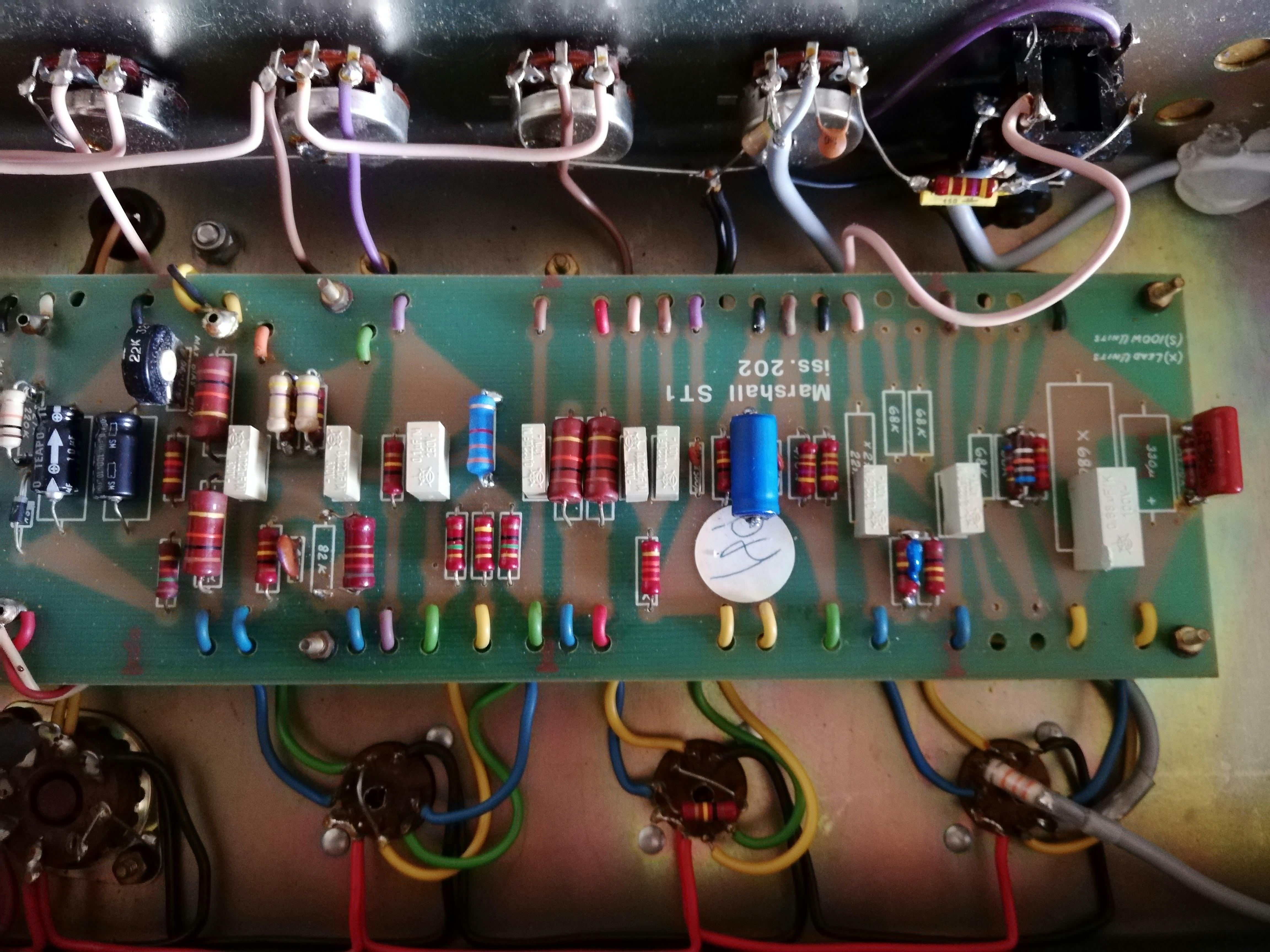
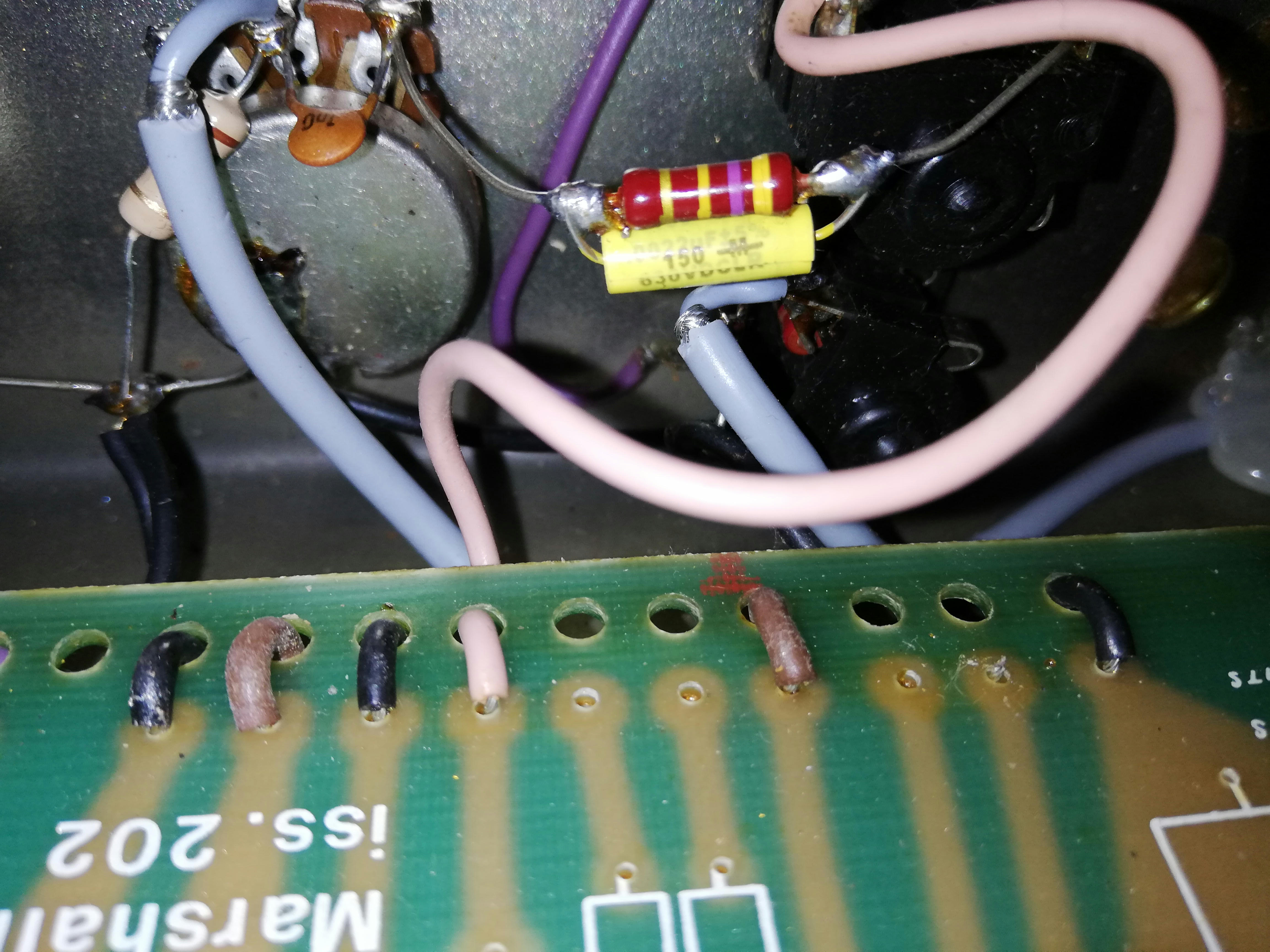
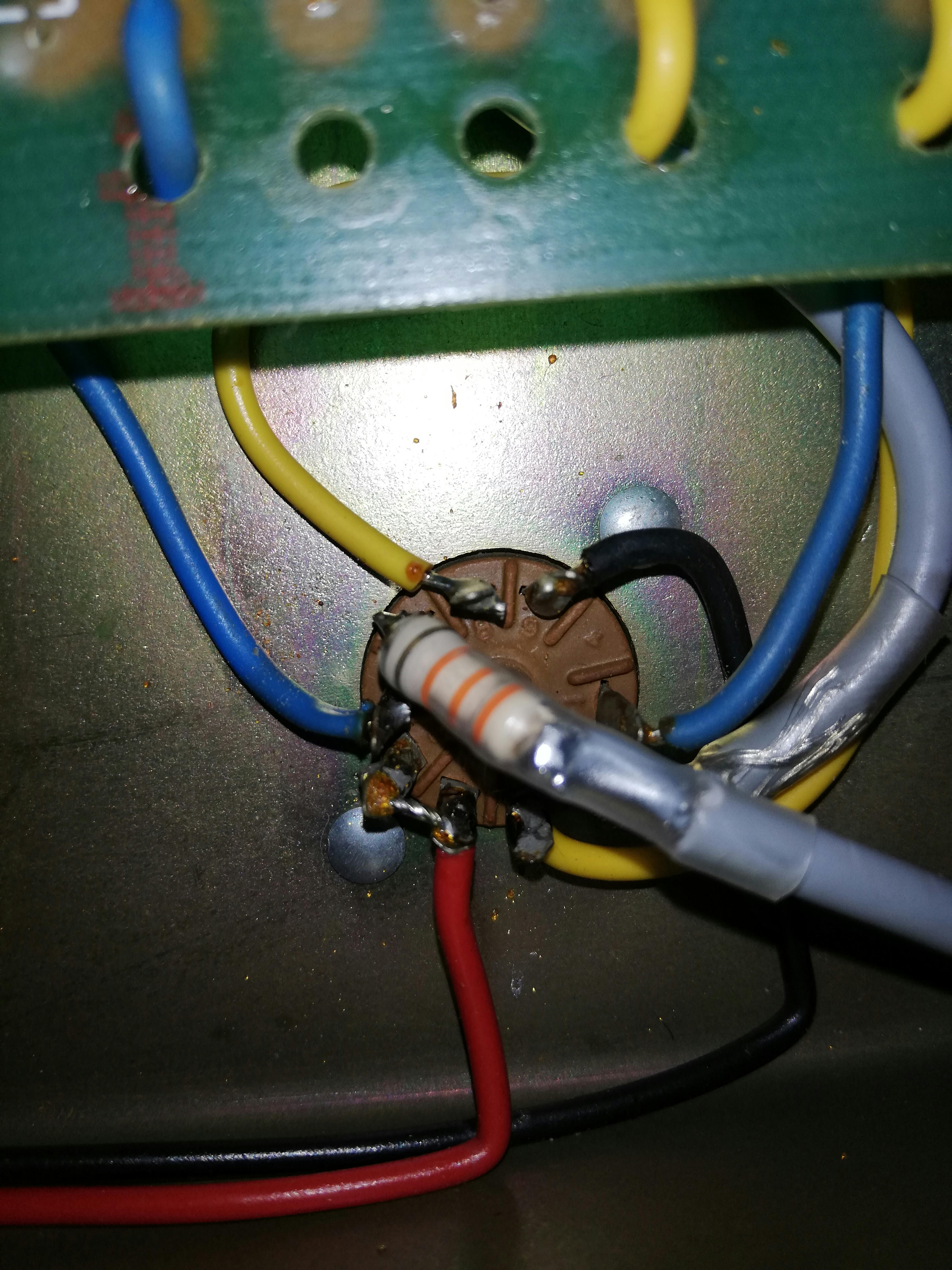
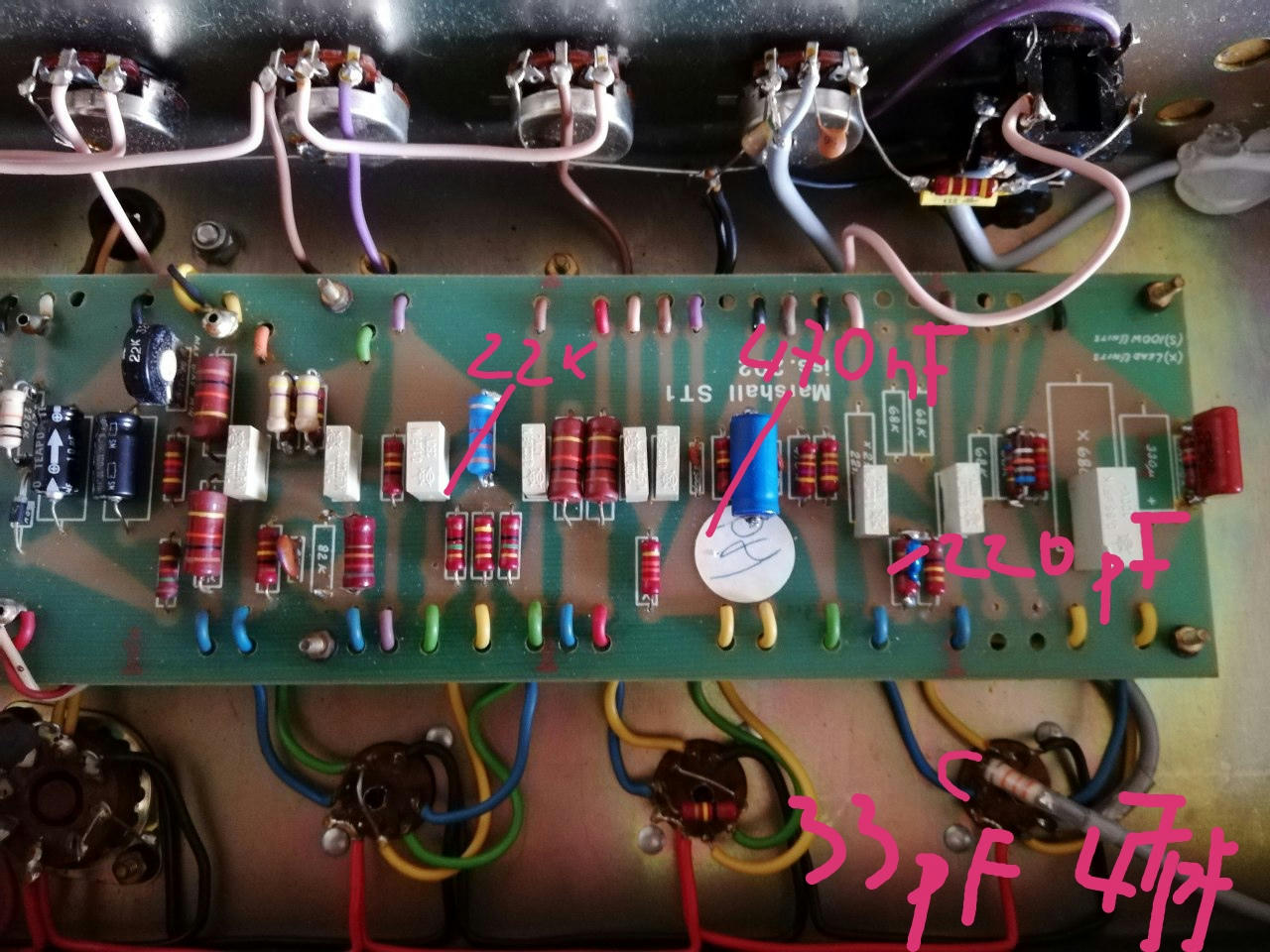
Your phase inverter, tail resistor appears to be 3.3k - needs to be 22k or 10k whichever you like better. That is the biggest issue I see.
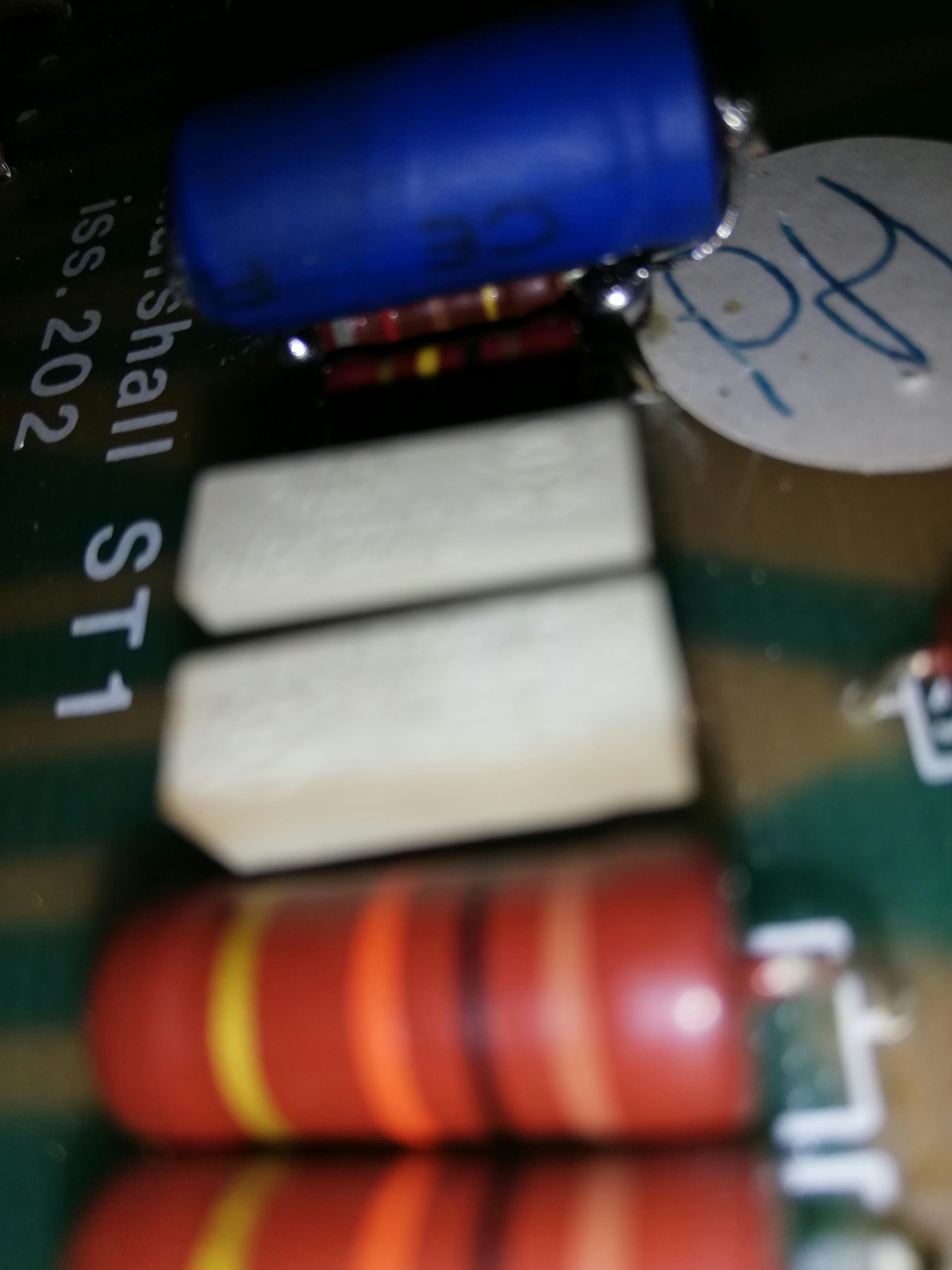
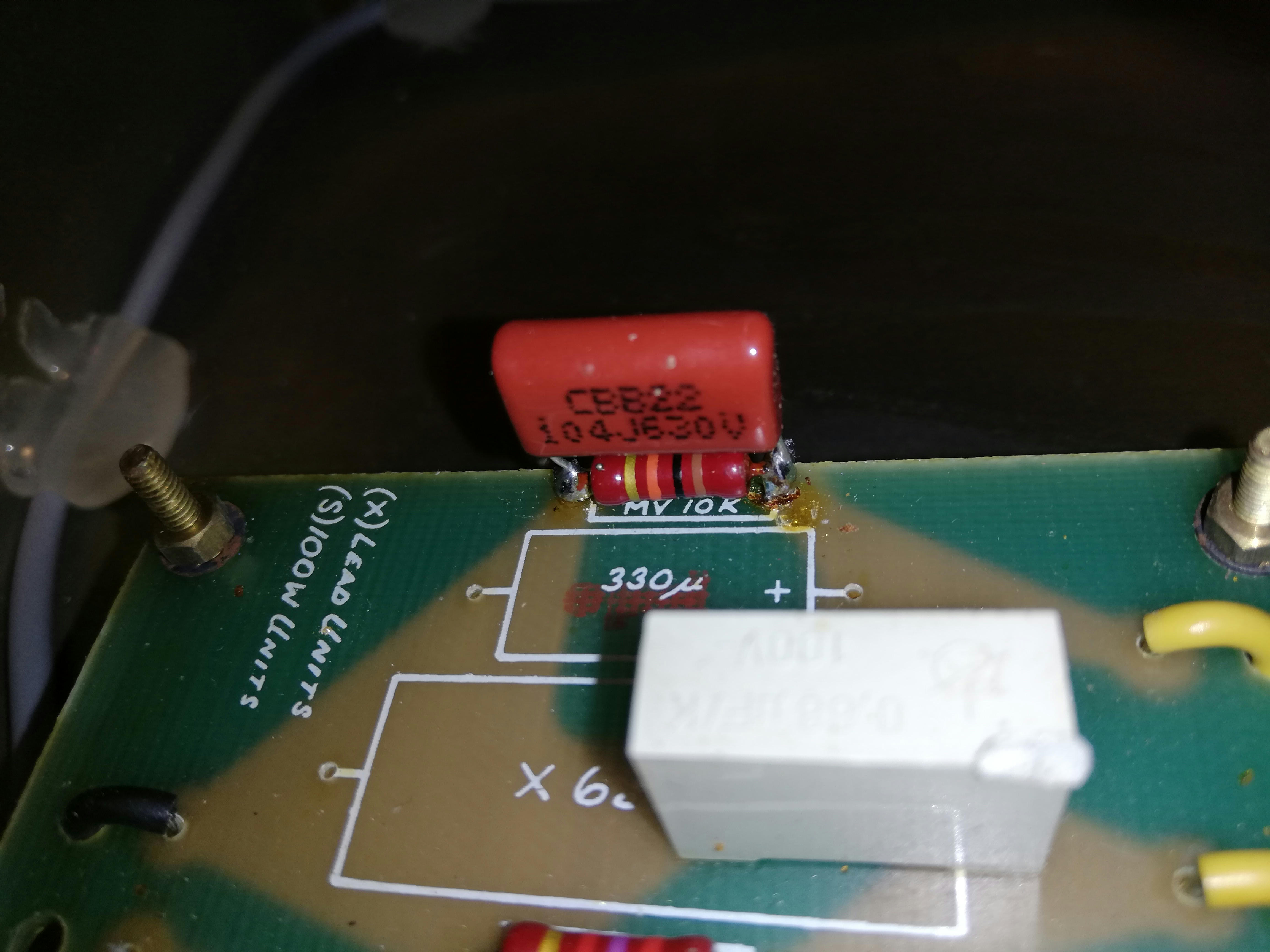
I can't tell which value the larger, blue capacitor is that you have bypassing the 820r cathode resistor of stage 3 - should be 470nF, not 470uF.
If you have 6550 power tubes, leave the 470k resistors bypassing the 220k resistors in the phase inverter - if you have EL34, I'd use 220k only.
I can't tell which value the yellow capacitor is that you have bypassing the 470k resistor at the input jack / volume pot - should be 2.2nF.
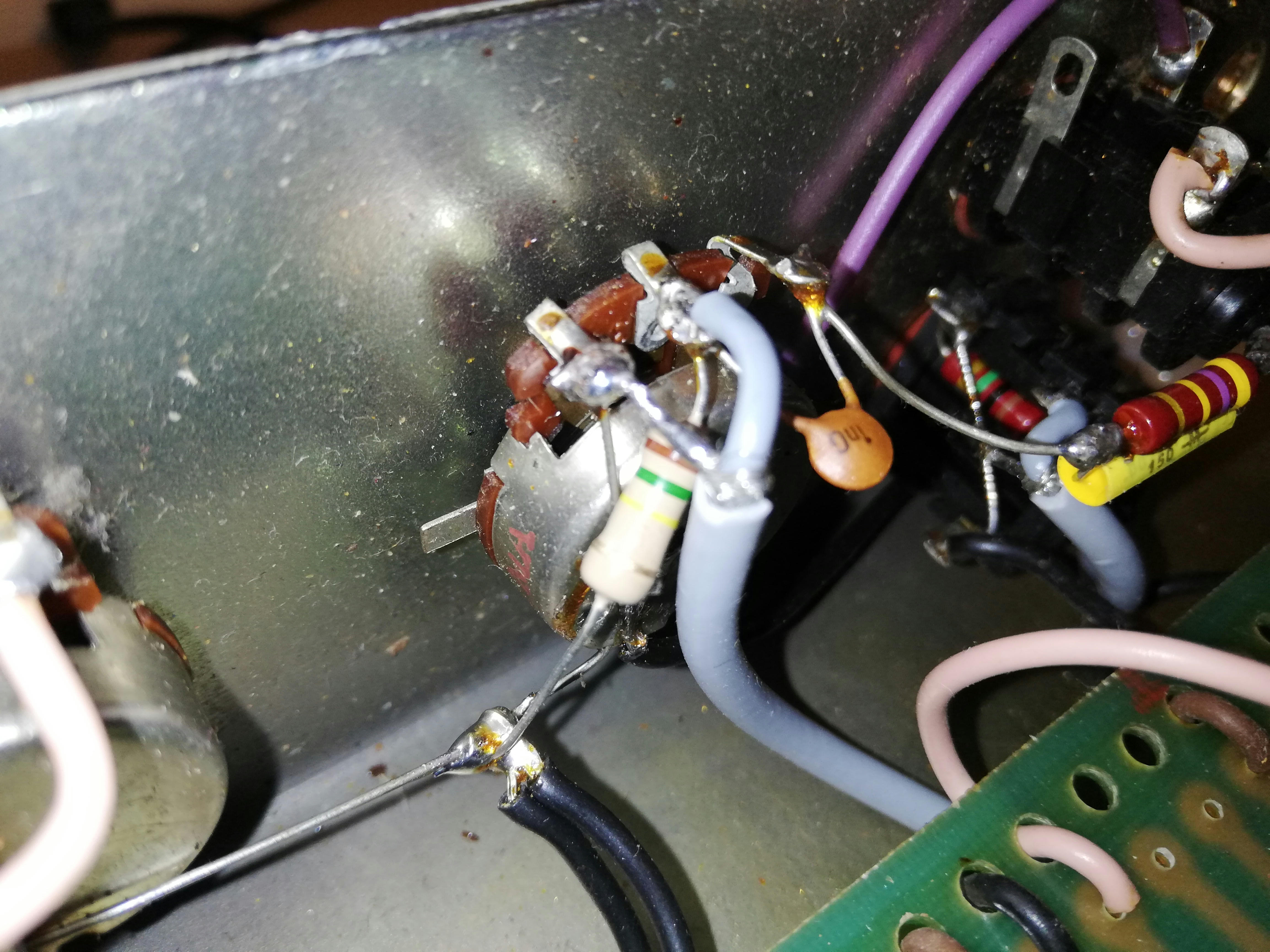
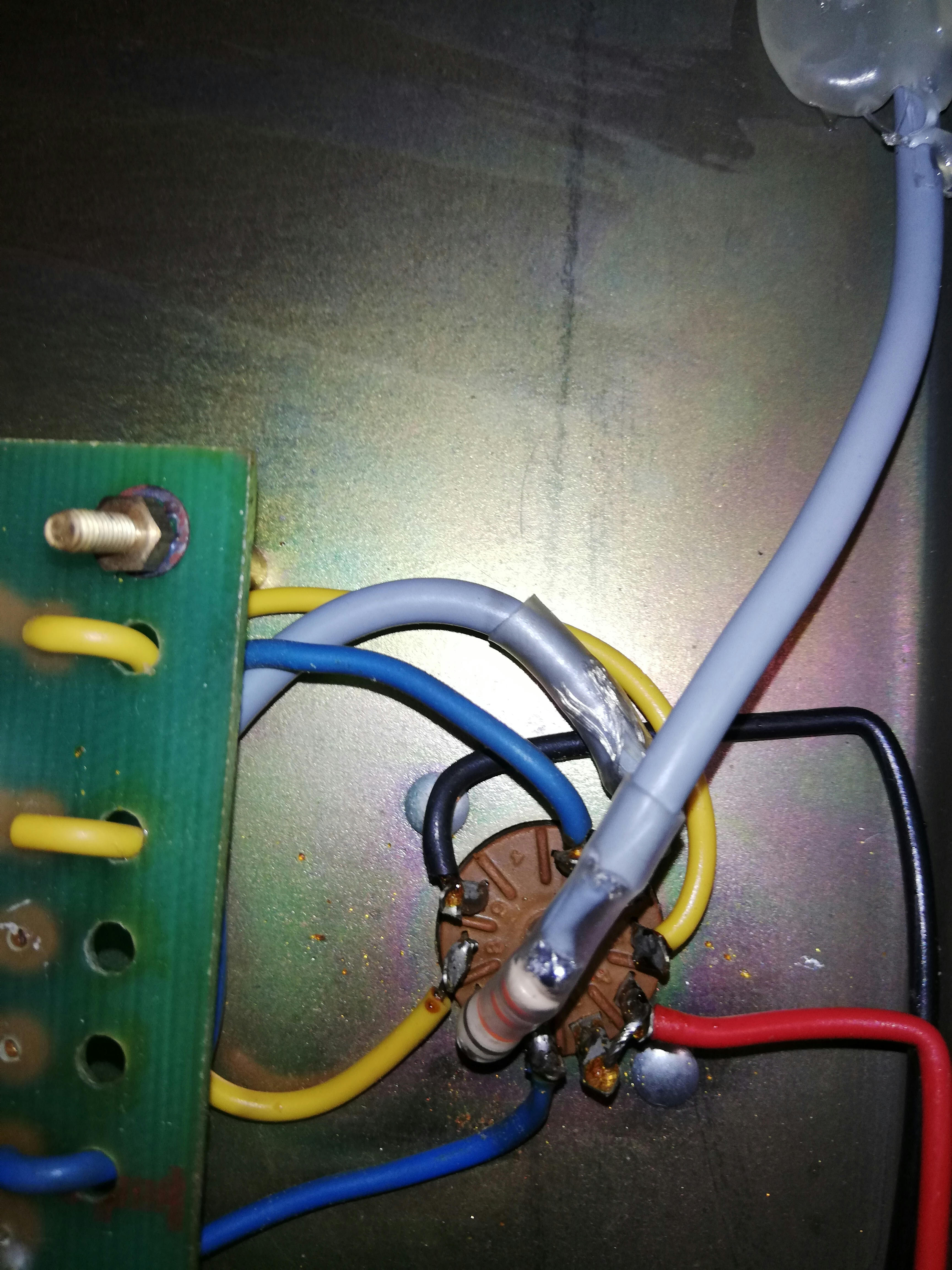
The gray, shielded cable from the input jack is about a foot too long.
In the #34 schematic, the 1nF bright capacitor on the volume pot is shown to be switchable - I'd do that to make the amp more usable.
Need to verify that the negative feed back (purple wire leading from the board to the speaker ohms selector) is connected to the 4 ohm tap position on the selector switch.
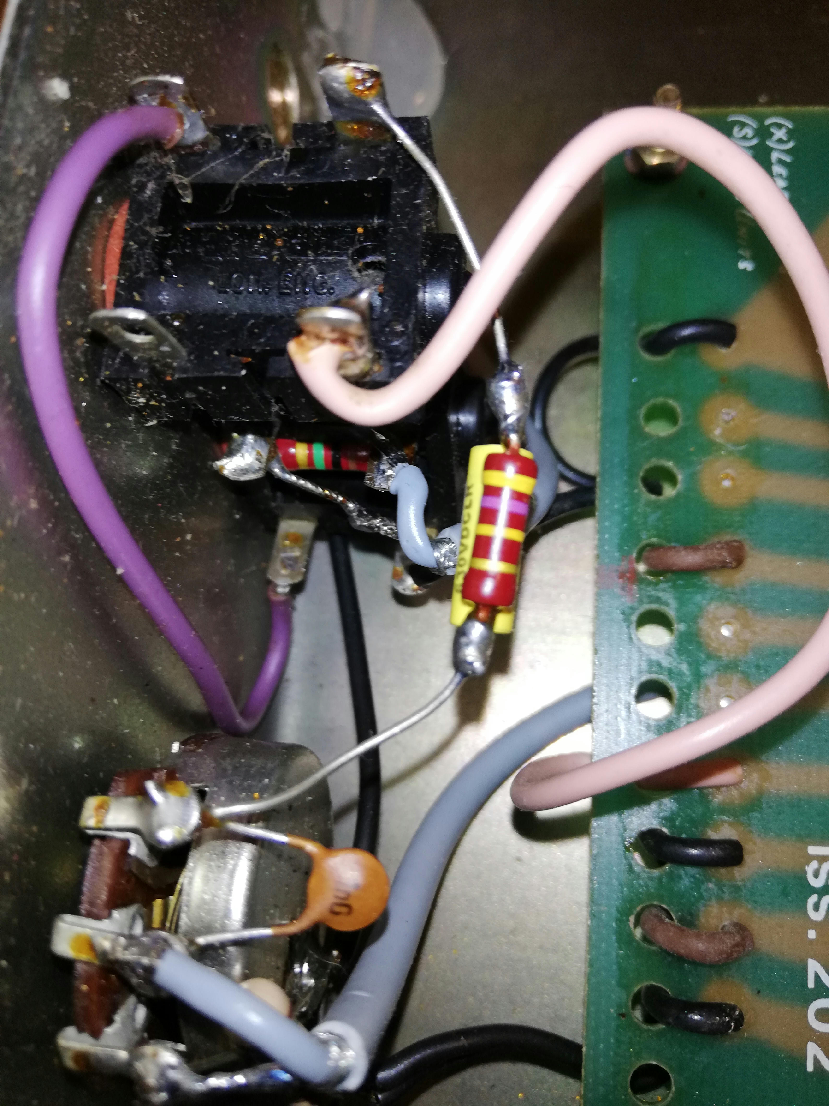
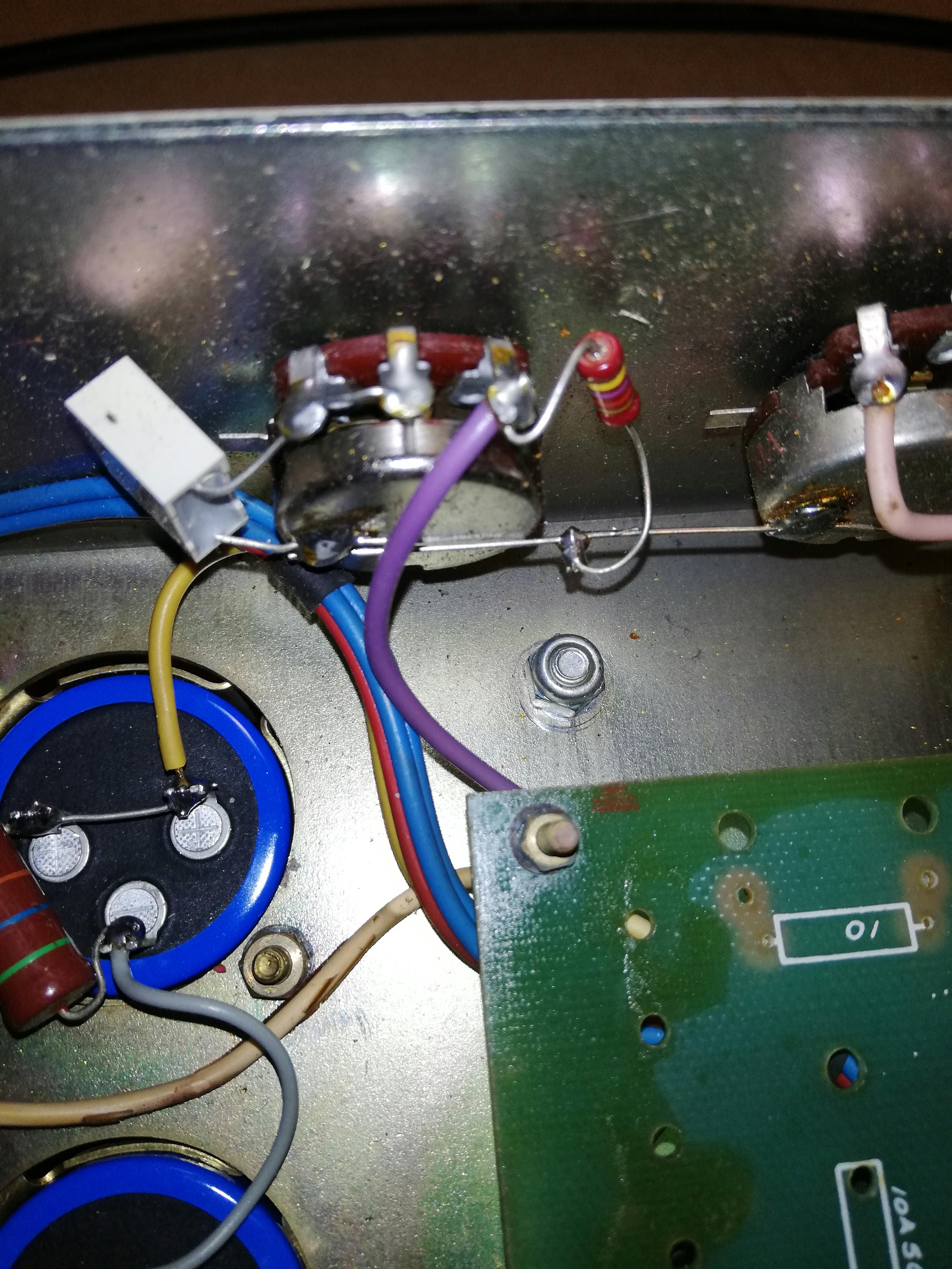
Can you post a pic of the presence pot wiring / components so they can be verified?
Cannot listen to clips - link is not good.
I can't tell which value the larger, blue capacitor is that you have bypassing the 820r cathode resistor of stage 3 - should be 470nF, not 470uF.
If you have 6550 power tubes, leave the 470k resistors bypassing the 220k resistors in the phase inverter - if you have EL34, I'd use 220k only.
I can't tell which value the yellow capacitor is that you have bypassing the 470k resistor at the input jack / volume pot - should be 2.2nF.
The gray, shielded cable from the input jack is about a foot too long.
In the #34 schematic, the 1nF bright capacitor on the volume pot is shown to be switchable - I'd do that to make the amp more usable.
Need to verify that the negative feed back (purple wire leading from the board to the speaker ohms selector) is connected to the 4 ohm tap position on the selector switch.
Can you post a pic of the presence pot wiring / components so they can be verified?
Cannot listen to clips - link is not good.
-
Unique
- Senior Member
- Posts: 229
- Joined: Wed Oct 02, 2013 12:48 pm
- Just the numbers in order: 13492
Re: S.I.R. 100W SuperLead Schematic pt. II
It looks like your using the 'safe' shield because I don't see a shield grounded at the socket. But then again I don't see a shield grounded at the input either? Is it grounded at the input?
I tried the safe shield one time, and it sounded good, but anything over 4 on the PA just oscillated. #34 has a hot-shield, and to get the sound right you would need a hot-shield. Either way, the cable should be around 8" in length, depending on the type of cable you used. But you may have to tweak it. 8" is a good starting place.
I tried the safe shield one time, and it sounded good, but anything over 4 on the PA just oscillated. #34 has a hot-shield, and to get the sound right you would need a hot-shield. Either way, the cable should be around 8" in length, depending on the type of cable you used. But you may have to tweak it. 8" is a good starting place.
-
blacklabel
- New Member
- Posts: 38
- Joined: Mon Jan 20, 2014 7:28 am
- Just the numbers in order: 13492
Re: S.I.R. 100W SuperLead Schematic pt. II
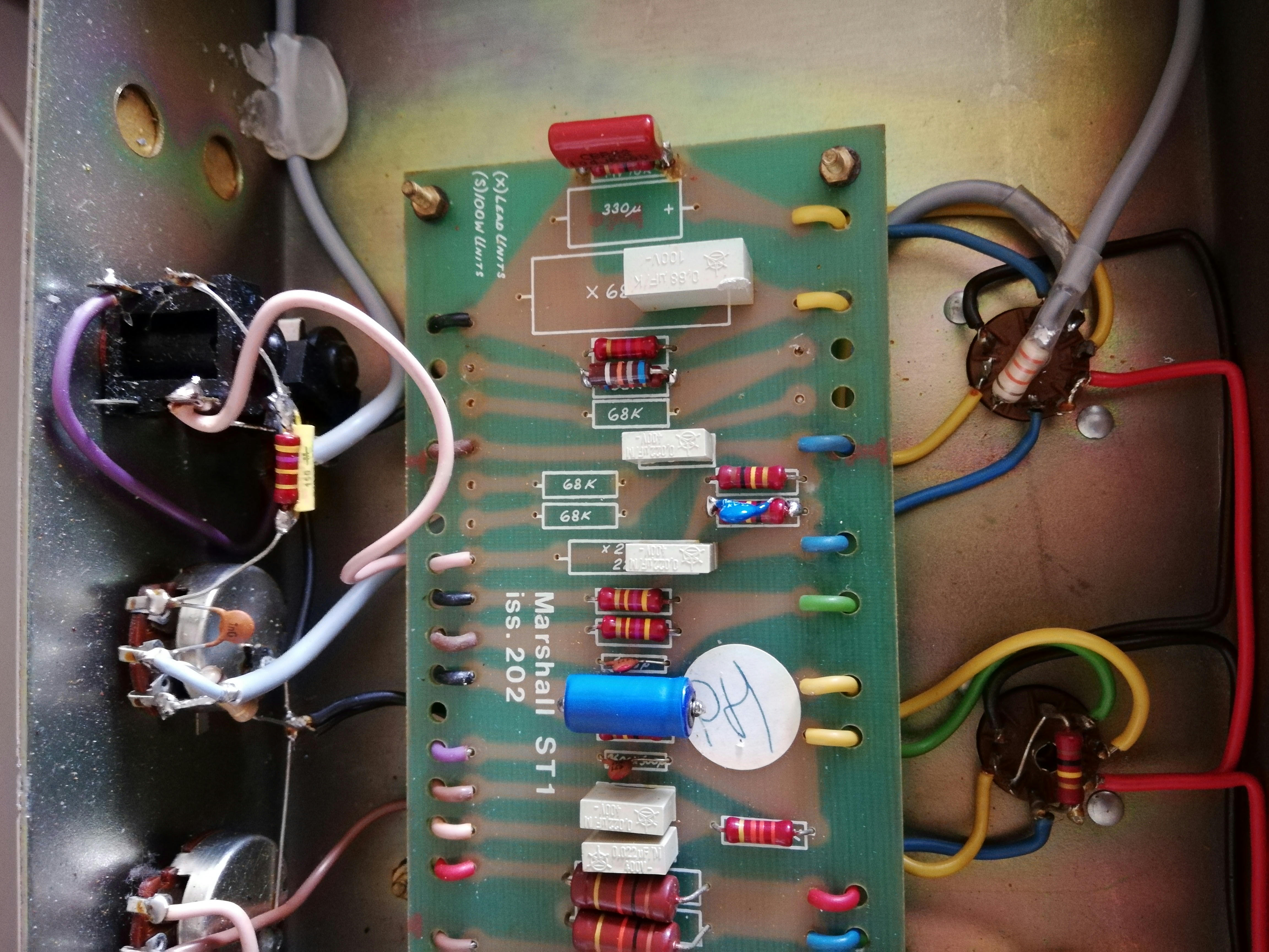
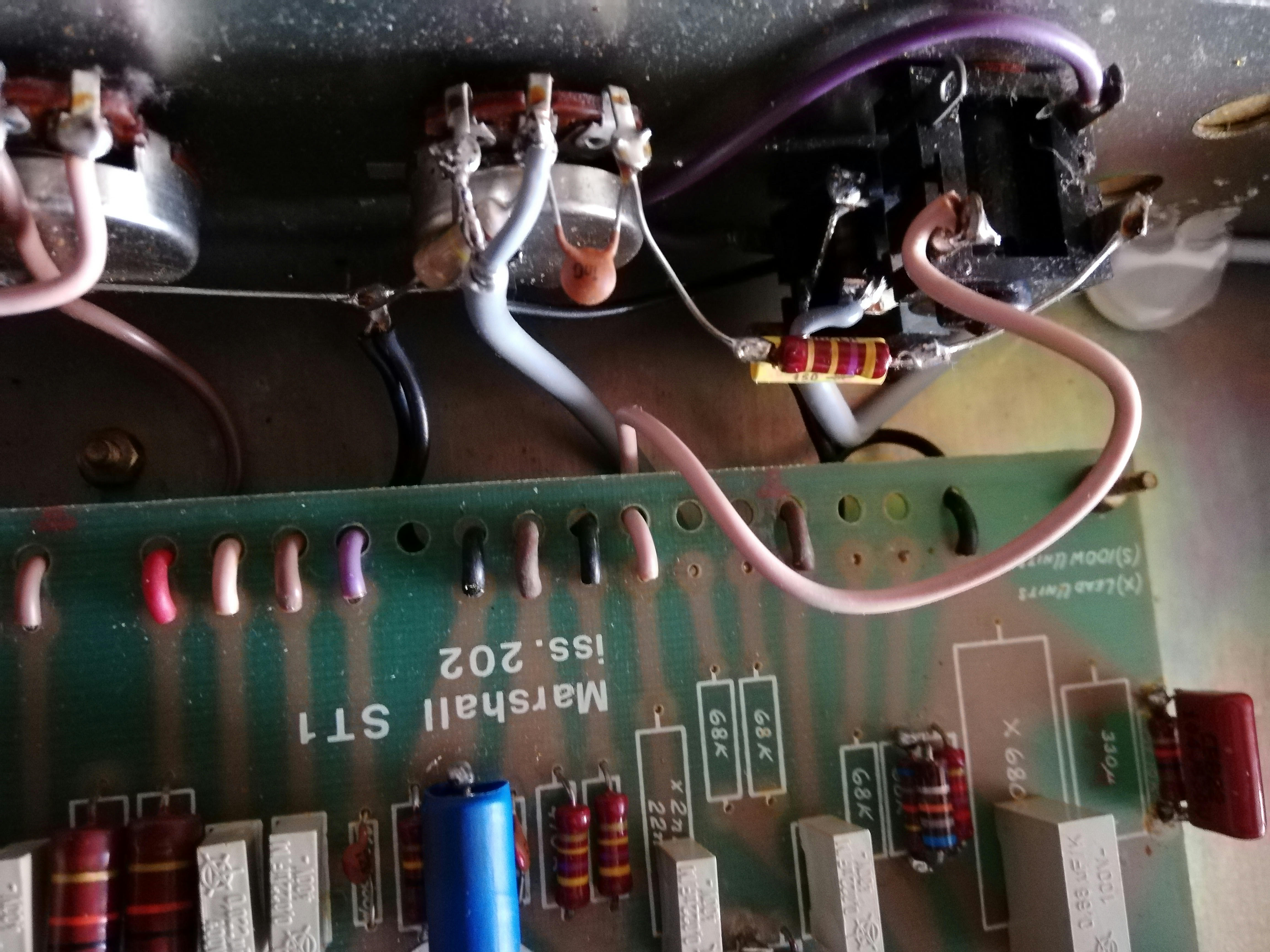
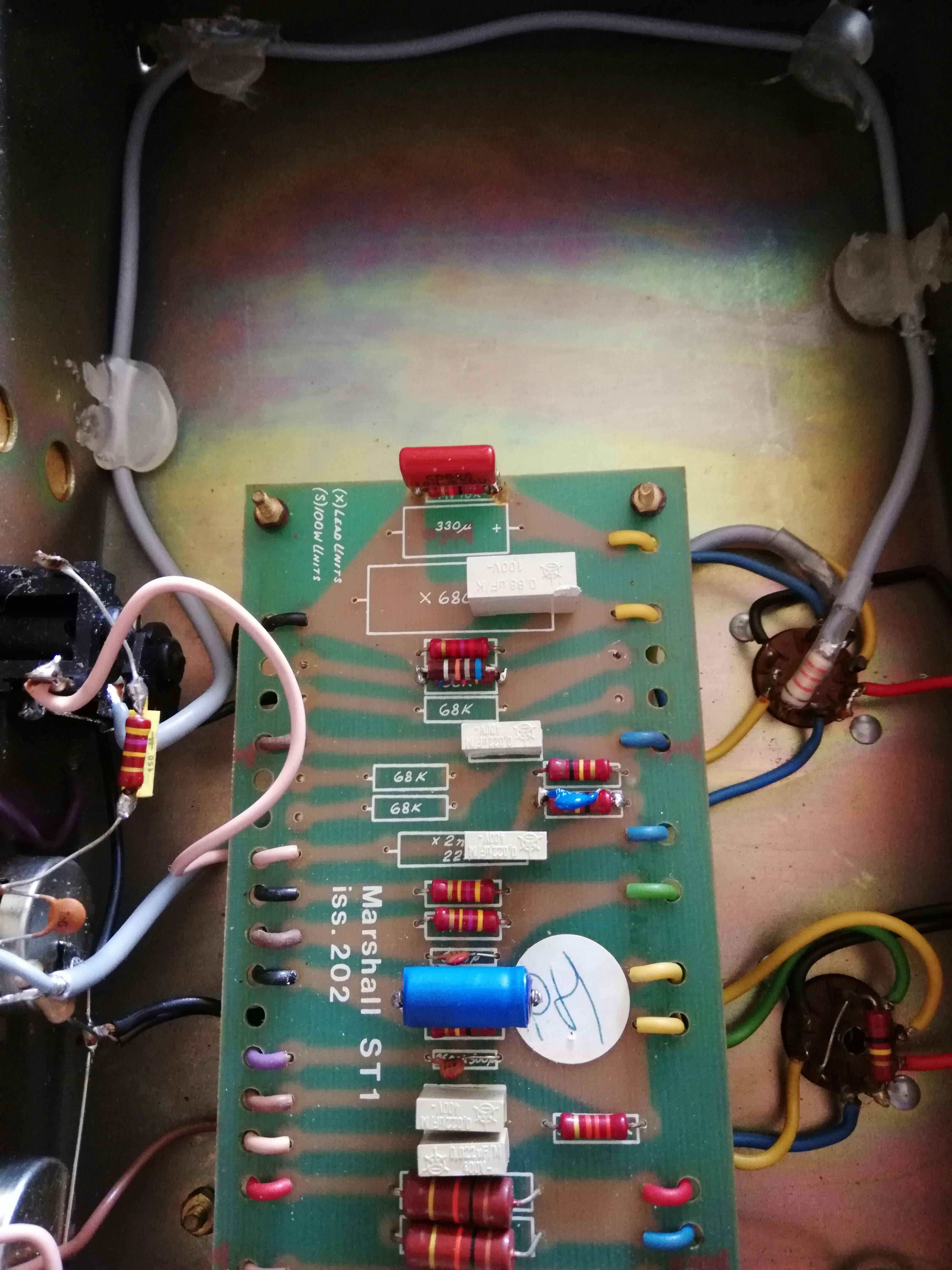
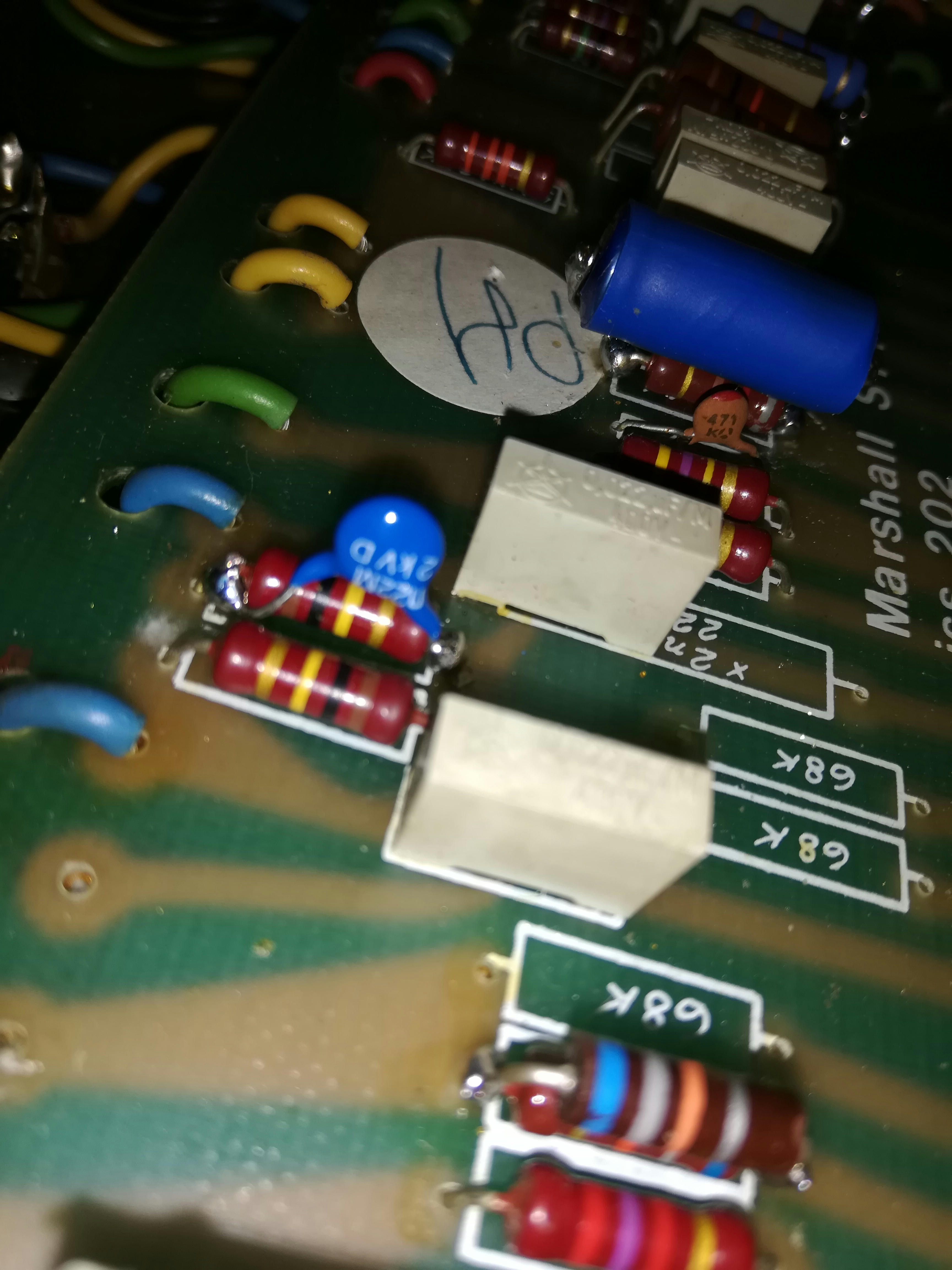
I am attaching more detailed pictures of the resistors and shielded cable.
Yes, i have 6550 old svetlana tubes. This mod was made by a technician...
Thanks guys!
try this link for audio samples: https://www.soundclick.com/bands3/?bandID=1447256
https://www.mediafire.com/convkey/955f/ ... 6fr4zg.jpg
https://www.mediafire.com/convkey/55b2/ ... hp30zg.jpg
https://www.mediafire.com/convkey/a9bc/ ... uh1mzg.jpg
https://www.mediafire.com/convkey/9a90/ ... j7j5zg.jpg
https://www.mediafire.com/convkey/e9e6/ ... gxa1zg.jpg
https://www.mediafire.com/convkey/7c88/ ... p3tczg.jpg
https://www.mediafire.com/convkey/fa6c/ ... kkuczg.jpg
https://www.mediafire.com/convkey/0733/ ... 5jnazg.jpg
https://www.mediafire.com/convkey/da66/ ... 3luazg.jpg
-
CoffeeTones
- Senior Member
- Posts: 1112
- Joined: Mon Oct 11, 2010 9:52 pm
- Just the numbers in order: 7
- Location: USA
Re: S.I.R. 100W SuperLead Schematic pt. II
Everything looks fine except again, your phase inverter, tail resistor appears to be 3.3k - needs to be 22k or 10k whichever you like better. That is the biggest issue I see and will definitely affect the sound in a negative way.
I still can't tell which value the larger, blue capacitor is that you have bypassing the 820r cathode resistor of stage 3 - it should be 470nF, not 470uF. It appears that it is wrong because a 470nF cap is normally not that big, nor an electrolytic capacitor as that one appears to be. This will take the sound away from the #34 realm.
The inputs shielded wire has the shield grounded as normal. That is fine unless you want the hot shield. What you have now is more safe.
I listened to the clips and it does sound pretty jacked up.
Have your tech double check / correct the first two things above and bring us some new clips.
-
blacklabel
- New Member
- Posts: 38
- Joined: Mon Jan 20, 2014 7:28 am
- Just the numbers in order: 13492
Re: S.I.R. 100W SuperLead Schematic pt. II
Thank you!
I had sent the head to a technician, so I will have to replace the resistance and cap by myself. I'm going to buy it
Does 470nF have to be made of 630V polypropylene or doesn't it matter? like this https://www.mojotone.com/amp-parts/Poly ... 630V-470nF
I had sent the head to a technician, so I will have to replace the resistance and cap by myself. I'm going to buy it
Does 470nF have to be made of 630V polypropylene or doesn't it matter? like this https://www.mojotone.com/amp-parts/Poly ... 630V-470nF
-
CoffeeTones
- Senior Member
- Posts: 1112
- Joined: Mon Oct 11, 2010 9:52 pm
- Just the numbers in order: 7
- Location: USA
Re: S.I.R. 100W SuperLead Schematic pt. II
Polypropylene or polyester caps will work. They differ slightly in sound, but not a big issue. Those Mojo caps are fine, but that one will be quite large for that position. Likely larger than the cap that is there now. (I have those exact Mojo caps in 470nF). The 470nF can be lower voltage rated because it normally experiences .9 to 1.3 volts in that position. Poly caps for our use will likely be 63V up to 630V. Lower voltage rated caps of the same value, are usually smaller.
Also try to get a 22k, 1 watt, carbon film resistor for the PI tail in #34. 10k is the stock value. I would not use a metal oxide composition, resistor such as the one now in that PI tail position.
The presence cap can be .1uF or .68uF, whichever you prefer. That value has been debated in this thread. A 250 volt rated cap will be fine and fit nicely for the presence cap, if you need one.
Unplug the power cord and drain the power filter caps of their charge, before you start working on the amp.
-
Unique
- Senior Member
- Posts: 229
- Joined: Wed Oct 02, 2013 12:48 pm
- Just the numbers in order: 13492
Re: S.I.R. 100W SuperLead Schematic pt. II
Here is the cathode bypass cap that is in #34. Coincidentally it was also the same cap originally used in the Cry Baby Wah pedal and was known as "the vocal cap."blacklabel wrote: ↑Mon Jun 10, 2019 3:08 amThank you!
I had sent the head to a technician, so I will have to replace the resistance and cap by myself. I'm going to buy it
Does 470nF have to be made of 630V polypropylene or doesn't it matter? like this https://www.mojotone.com/amp-parts/Poly ... 630V-470nF
https://www.ebay.com/itm/2-47uf-10-250v ... 1012528884
-
blacklabel
- New Member
- Posts: 38
- Joined: Mon Jan 20, 2014 7:28 am
- Just the numbers in order: 13492
Re: S.I.R. 100W SuperLead Schematic pt. II
Ok I'll do all to my friend (luthier),it's safer for me.
In addition to replacing the 22k resistor and the 470nF (250v) cap, I have another small 2k (color blue) and 100nF (0.1uF) capacitor at the Presence potentiometer. Should I also replace these with a 220p and 680nF capacitor respectively?
In addition to replacing the 22k resistor and the 470nF (250v) cap, I have another small 2k (color blue) and 100nF (0.1uF) capacitor at the Presence potentiometer. Should I also replace these with a 220p and 680nF capacitor respectively?
Last edited by blacklabel on Mon Jun 10, 2019 11:10 am, edited 1 time in total.
-
Unique
- Senior Member
- Posts: 229
- Joined: Wed Oct 02, 2013 12:48 pm
- Just the numbers in order: 13492
Re: S.I.R. 100W SuperLead Schematic pt. II
The presence cap in #34 is a .1uF (100n), but you can use a .68uF if you like. It's really up to you. Also, with #34 the 4k7 resistor was removed from the presence pot. So there is no resistor on there. Again, this is up to you. Removing that resistor makes the amp more raspy and open sounding, and the bass a little tighter. It also gives the half-cocked wah sound you hear with this mod that 'wet and woolly' effect like #34 has on the demos and albums. In a sense, removing the resistor from the presence pot makes an already very bright sounding mod even a little brighter sounding and more raspy. But it's not something you have to do. With the resistor on there your amp will still sound like a #34 modded amp. It's just another option you have to choose from to personally tweak the mod to your liking.blacklabel wrote: ↑Mon Jun 10, 2019 10:30 amOk I'll do all to my friend (liuther),it's more secure.
In addition to replacing the 22k resistor and the 470n (250v) cap, I have another small 2k (color blue) and 100n (0.1uF) capacitor at the Presence potentiometer. Should I also replace these with a 220p and 680n capacitor respectively?
-
blacklabel
- New Member
- Posts: 38
- Joined: Mon Jan 20, 2014 7:28 am
- Just the numbers in order: 13492
Re: S.I.R. 100W SuperLead Schematic pt. II
Ok thank you Unique!
So this is what I should do, replace those 3 blue ones.
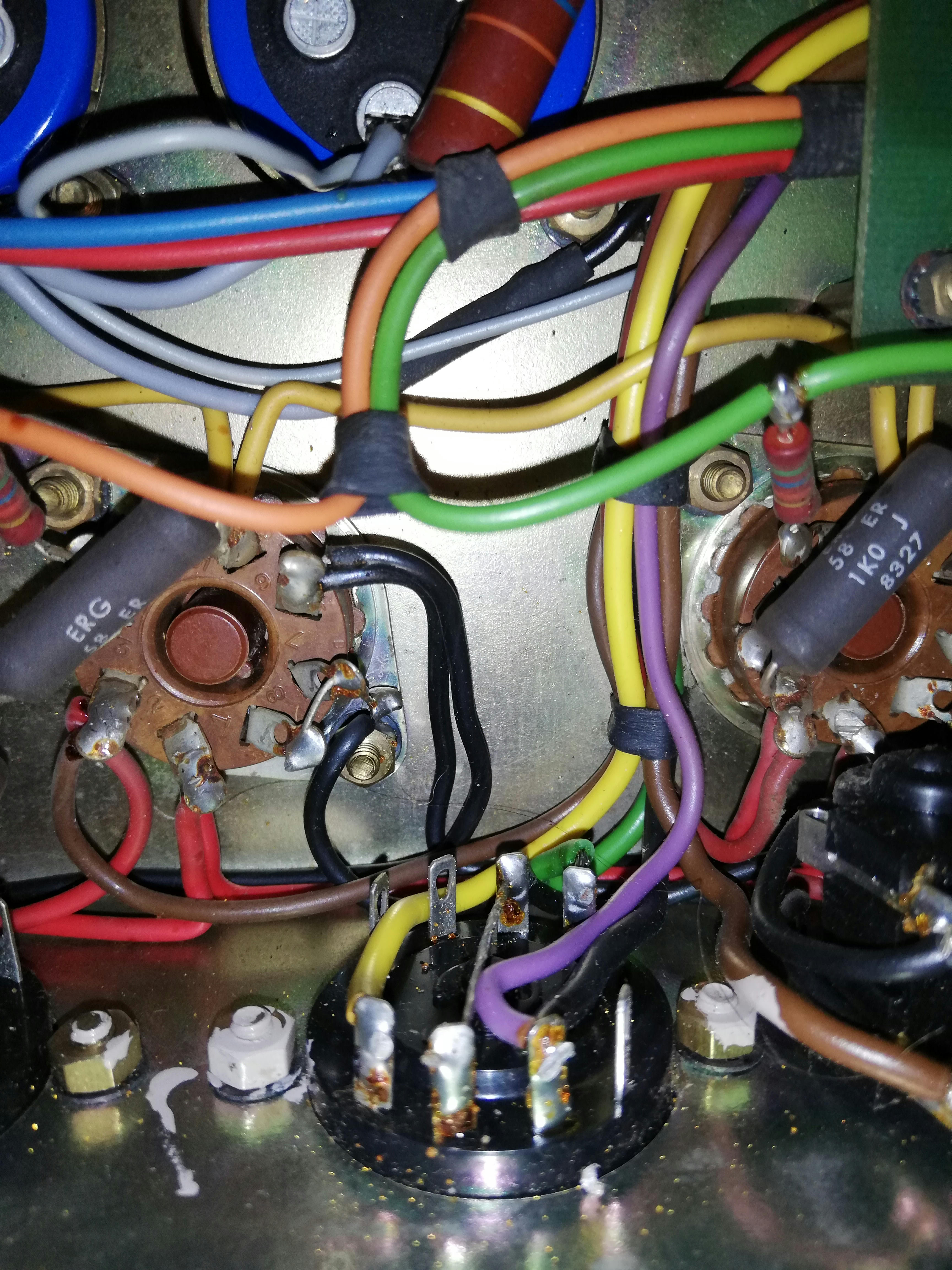
For the shielded cable I don't know what to do, but I will also try to add a 33pF or 47pF capacitor welded directly to the valve pin in this way as in the image above. I don't know who suggested it
So this is what I should do, replace those 3 blue ones.
For the shielded cable I don't know what to do, but I will also try to add a 33pF or 47pF capacitor welded directly to the valve pin in this way as in the image above. I don't know who suggested it
-
CoffeeTones
- Senior Member
- Posts: 1112
- Joined: Mon Oct 11, 2010 9:52 pm
- Just the numbers in order: 7
- Location: USA
Re: S.I.R. 100W SuperLead Schematic pt. II
The #34, .1uF versus .68uF presence cap is debatable and there's more to that subject than I care to get into again. You are misleading by saying to remove the present pot mounted, 4k7 tail shunt / part of the negative feedback circuit. By doing that, he will not have a proper ground source for the PI and the negative feedback circuit will be incomplete. I see Santiago has the 25k pot wired as shunt on the schematic, but it must be an error. I'll have to dig up the pics.Unique wrote: ↑Mon Jun 10, 2019 10:59 amThe presence cap in #34 is a .1uF (100n), but you can use a .68uF if you like. It's really up to you. Also, with #34 the 4k7 resistor was removed from the presence pot. So there is no resistor on there. Again, this is up to you. Removing that resistor makes the amp more raspy and open sounding, and the bass a little tighter. It also gives the half-cocked wah sound you hear with this mod that 'wet and woolly' effect like #34 has on the demos and albums. In a sense, removing the resistor from the presence pot makes an already very bright sounding mod even a little brighter sounding and more raspy. But it's not something you have to do. With the resistor on there your amp will still sound like a #34 modded amp. It's just another option you have to choose from to personally tweak the mod to your liking.
I have not looked at the pics of the #34 original lately, but it may have had the 5k presence pot / circuit with .1uF or .68uF cap. That 5k pot is wired much differently than the 25k pot circuit, in which case the 5k pot is acting as the 4.7k tail shunt and part of the NFB ratio divider. Anyone building the mod should try both circuits and decide which is preferable for themselves. Check out the 68' Plexi and 2203 schematics or layouts to view the presence circuit differences described above.
Last edited by CoffeeTones on Mon Jun 10, 2019 2:06 pm, edited 3 times in total.