my new 1959 sounds good and works well with one exception: two tubes redplates on the 480v setting. usually these are v4 and v5 but the redplating changes to v6 and v7 if I swap sides. the redplating is always on the push side (not the pull side), the side that normally is connected to the 82k in the pi.
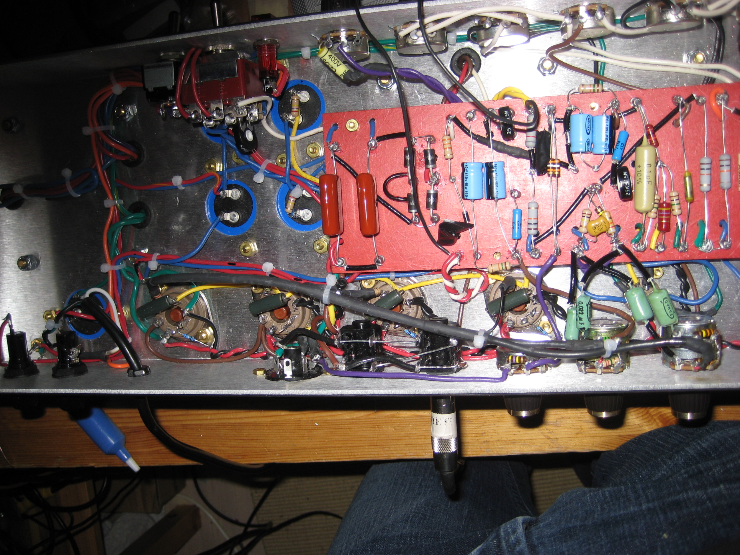
the amp has dual lar mar mv, see pics below
these things dont work:
- changing tubes (v3-7)
- lowering 82k to 68k
- connecting a different preamp
- changing .022uf pi input cap
- swapping choke
- installing 10k swamp resistors and 47k on pi grid as well as upping 47pf to 120pf
- swapping plates or grid on pi
- swapping sides on the lar mar pots so that pi coupling caps go to the other end of the pots
- removing larry/aiken/vox presence
- moving nfb wire and removing pot connected between impedance selector and nfb resistor
the only thing constant is that it is always the push side that redplates (if that makes sense), it need not even be the 82k side or only the two tubes connected to one side of the OT primaries
http://folk.ntnu.no/roef/IMG_3035
http://folk.ntnu.no/roef/IMG_3038
http://folk.ntnu.no/roef/IMG_3036.jpg
redplating 1959 w larmar
Moderator: VelvetGeorge
-
Roe
- Senior Member
- Posts: 5056
- Joined: Thu Apr 13, 2006 1:36 pm
- Just the numbers in order: 7
- Location: Drontheim. Norwegen
- Contact:
redplating 1959 w larmar
Last edited by Roe on Tue Feb 02, 2010 5:11 pm, edited 5 times in total.
http://www.myspace.com/20bonesband" onclick="window.open(this.href);return false;
http://www.myspace.com/prostitutes" onclick="window.open(this.href);return false;
Super 100 amps: 1202-119 & 1202-84
JTM45 RS OT JTM50 JMP50 1959/2203/34/39
http://www.myspace.com/prostitutes" onclick="window.open(this.href);return false;
Super 100 amps: 1202-119 & 1202-84
JTM45 RS OT JTM50 JMP50 1959/2203/34/39
-
neikeel

- Senior Member
- Posts: 7231
- Joined: Tue Dec 06, 2005 8:31 am
- Location: Suffolk, England
Re: redplating 1959 w larmar
You've got quite a lot going on in there haven't you, lots of shrink wrap and multiple mods in and out. Some of the connection around the PI output but I guess you have done and redone lots of those connections a few times.....
I suspect you need someone like SDM, Flames or Larry to look by
I suspect you need someone like SDM, Flames or Larry to look by
Neil
-
Roe
- Senior Member
- Posts: 5056
- Joined: Thu Apr 13, 2006 1:36 pm
- Just the numbers in order: 7
- Location: Drontheim. Norwegen
- Contact:
Re: redplating 1959 w larmar
its just a few mods 
- two separate bias circuits, both are like the original circuit but the 2nd is squeezed into less space.
- dual lar mar W/larry/aiken/vox presence
- variable nfb
-larry grounding (amp IS quiet)
- switchable .68 on v2a
- switchable one-wire mod/straight 1959 bright channel.
but since it redplates just the same with a different preamp, I guess the PI/driver is to blame. I'm gonna redo the pi coupling caps now.
Last edited by Roe on Tue Feb 02, 2010 4:14 pm, edited 1 time in total.
http://www.myspace.com/20bonesband" onclick="window.open(this.href);return false;
http://www.myspace.com/prostitutes" onclick="window.open(this.href);return false;
Super 100 amps: 1202-119 & 1202-84
JTM45 RS OT JTM50 JMP50 1959/2203/34/39
http://www.myspace.com/prostitutes" onclick="window.open(this.href);return false;
Super 100 amps: 1202-119 & 1202-84
JTM45 RS OT JTM50 JMP50 1959/2203/34/39
-
Roe
- Senior Member
- Posts: 5056
- Joined: Thu Apr 13, 2006 1:36 pm
- Just the numbers in order: 7
- Location: Drontheim. Norwegen
- Contact:
Re: redplating 1959 w larmar
new picshttp://folk.ntnu.no/roef/IMG_3041
http://folk.ntnu.no/roef/IMG_3040
I moved the pi coupling caps and moved the nfb wire, but no effect
http://folk.ntnu.no/roef/IMG_3040
I moved the pi coupling caps and moved the nfb wire, but no effect
http://www.myspace.com/20bonesband" onclick="window.open(this.href);return false;
http://www.myspace.com/prostitutes" onclick="window.open(this.href);return false;
Super 100 amps: 1202-119 & 1202-84
JTM45 RS OT JTM50 JMP50 1959/2203/34/39
http://www.myspace.com/prostitutes" onclick="window.open(this.href);return false;
Super 100 amps: 1202-119 & 1202-84
JTM45 RS OT JTM50 JMP50 1959/2203/34/39
-
Roe
- Senior Member
- Posts: 5056
- Joined: Thu Apr 13, 2006 1:36 pm
- Just the numbers in order: 7
- Location: Drontheim. Norwegen
- Contact:
Re: redplating 1959 w larmar
suggestions would be greatly appreciated
http://www.myspace.com/20bonesband" onclick="window.open(this.href);return false;
http://www.myspace.com/prostitutes" onclick="window.open(this.href);return false;
Super 100 amps: 1202-119 & 1202-84
JTM45 RS OT JTM50 JMP50 1959/2203/34/39
http://www.myspace.com/prostitutes" onclick="window.open(this.href);return false;
Super 100 amps: 1202-119 & 1202-84
JTM45 RS OT JTM50 JMP50 1959/2203/34/39
-
novosibir

- Senior Member
- Posts: 4654
- Joined: Tue Nov 22, 2005 2:32 pm
- Just the numbers in order: 7
- Location: Nuernberg, Germany
- Contact:
Re: redplating 1959 w larmar
First I'd shorten the plate cables of V3...Roe wrote:suggestions would be greatly appreciated
... but I think, that the twisted violet cables to your front side Presence are the cause of your prob!
They're too close to the OT's primaries! They're touching it even!
Larry
The fault almost always is sitting in front of the amp 
Larry's Website now with included Pix's Gallery
Larry's Website now with included Pix's Gallery
-
Roe
- Senior Member
- Posts: 5056
- Joined: Thu Apr 13, 2006 1:36 pm
- Just the numbers in order: 7
- Location: Drontheim. Norwegen
- Contact:
Re: redplating 1959 w larmar
Larry,novosibir wrote:First I'd shorten the plate cables of V3...Roe wrote:suggestions would be greatly appreciated
... but I think, that the twisted violet cables to your front side Presence are the cause of your prob!
They're too close to the OT's primaries! They're touching it even!
Larry
I shortened the plate wires of v3 and moved the twisted presence wires (to the top of the board so that they are far away from other wires).
however, the amp still redplates when running flat out
I measured the el34s under full load and at idle. here's the voltages:
Idle:
plates: 481v
screens: 477v
grid: -48v
Full load:
plates: 450v at lowest
screens: 430v at lowest
grid: pretty stable at -47-48v
voltages seem ok don't they
edit: forgot to measure for AC voltages.
Last edited by Roe on Mon Feb 15, 2010 5:25 am, edited 1 time in total.
http://www.myspace.com/20bonesband" onclick="window.open(this.href);return false;
http://www.myspace.com/prostitutes" onclick="window.open(this.href);return false;
Super 100 amps: 1202-119 & 1202-84
JTM45 RS OT JTM50 JMP50 1959/2203/34/39
http://www.myspace.com/prostitutes" onclick="window.open(this.href);return false;
Super 100 amps: 1202-119 & 1202-84
JTM45 RS OT JTM50 JMP50 1959/2203/34/39
-
Roe
- Senior Member
- Posts: 5056
- Joined: Thu Apr 13, 2006 1:36 pm
- Just the numbers in order: 7
- Location: Drontheim. Norwegen
- Contact:
Re: redplating 1959 w larmar
randall aiken added this highly interesting response to my thread on ampgarage:
You may want to consider the fact that you are running the poor EL34's way over their max dissipation limits with 480V on the plates and a 3.4K load (for two tubes in a 50W, which is the same as 1.7K for four tubes in a 100W). You do gain a bit from the lower full-power sag voltage of 450V, but not much.
The following image shows the 25W max dissipation curve in green, a 50W dissipation curve in red, and a 3.4K load line in yellow, all superimposed over the plate curves in blue: [pic: http://ampgarage.com/forum/viewtopic.ph ... sc&start=0]
As you can see, if you are running on this load line, biased up at 26mA (50% of 25W at 480V), the poor EL34 is spending most of it's time way above the max dissipation curve, in fact, above the 2x max dissipation curve (the part where the yellow line is above the red curve).
In a push-pull amp running close to class B, you can get away with running up to the 2x max dissipation limit because the duty cycle is near 50%, so the average dissipation never exceeds the 25W max limit, and you also spend some time at the edges of the load line where you are below the dissipation curve. However, you can't expect to spend very much time above the 2x limit and not exceed the dissipation.
The problem you run into in a typical high-voltage Marshall is that you are not only running above max ratings, you also have to contend with the duty-cycle modulation caused by the long-tail pair phase inverter design and the relative matching of the phase inverter tube sections under full clip. This causes the output square wave to not be equal on top and bottom - one side is wider and the other is narrower, so the wider side dissipates more power. This is why you redplate on only one side. The bad part is that there is no bias setting, even 0mA, that will keep you out of the danger zone above the 2x dissipation curve.
What can be done to fix this? Well, if you must run a 3.4K (1.7K) output transformer, you must reduce your plate voltage to no greater than around 400-420V to stay within the ratings. You may get by with a bit more, since the edges of the load line fall under the 2x curve. Alternately, if you want to run 480V, you must change your output transformer to around 4.8K - 6K (2.4K - 3K for 100W) to stay within the ratings. Any time you exceed these rules, you run the risk of redplating.
Randall Aiken
http://www.myspace.com/20bonesband" onclick="window.open(this.href);return false;
http://www.myspace.com/prostitutes" onclick="window.open(this.href);return false;
Super 100 amps: 1202-119 & 1202-84
JTM45 RS OT JTM50 JMP50 1959/2203/34/39
http://www.myspace.com/prostitutes" onclick="window.open(this.href);return false;
Super 100 amps: 1202-119 & 1202-84
JTM45 RS OT JTM50 JMP50 1959/2203/34/39
-
Roe
- Senior Member
- Posts: 5056
- Joined: Thu Apr 13, 2006 1:36 pm
- Just the numbers in order: 7
- Location: Drontheim. Norwegen
- Contact:
Re: redplating 1959 w larmar
I did more testing:
1k7 - 395v: no redplating
3k4 - 480v: no redplating
1k7- 480v: redplating after playing on 10 for a few minutes
So it seems Randall is pointing to a problem with the combination of high voltage and low Z (1k7).
Another strange thing: I can measure a litte AC on the tube sockets when running. Is this due to power supply ripple, bad coupling caps or bias circuit?
All sockets seem to be the same. I don't really think the coupling caps and bias circuits can explain this since I use 4 coupling caps and 2 separate bias circuits.
1k7 - 395v: no redplating
3k4 - 480v: no redplating
1k7- 480v: redplating after playing on 10 for a few minutes
So it seems Randall is pointing to a problem with the combination of high voltage and low Z (1k7).
Another strange thing: I can measure a litte AC on the tube sockets when running.
All sockets seem to be the same. I don't really think the coupling caps and bias circuits can explain this since I use 4 coupling caps and 2 separate bias circuits.
http://www.myspace.com/20bonesband" onclick="window.open(this.href);return false;
http://www.myspace.com/prostitutes" onclick="window.open(this.href);return false;
Super 100 amps: 1202-119 & 1202-84
JTM45 RS OT JTM50 JMP50 1959/2203/34/39
http://www.myspace.com/prostitutes" onclick="window.open(this.href);return false;
Super 100 amps: 1202-119 & 1202-84
JTM45 RS OT JTM50 JMP50 1959/2203/34/39
-
jbzoso2002

- Senior Member
- Posts: 1089
- Joined: Tue May 17, 2005 12:01 pm
- Just the numbers in order: 7
- Location: NW Indiana
Re: redplating 1959 w larmar
Roe wrote:randall aiken added this highly interesting response to my thread on ampgarage:
You may want to consider the fact that you are running the poor EL34's way over their max dissipation limits with 480V on the plates and a 3.4K load (for two tubes in a 50W, which is the same as 1.7K for four tubes in a 100W). You do gain a bit from the lower full-power sag voltage of 450V, but not much.
The following image shows the 25W max dissipation curve in green, a 50W dissipation curve in red, and a 3.4K load line in yellow, all superimposed over the plate curves in blue: [pic: http://ampgarage.com/forum/viewtopic.ph ... sc&start=0]
As you can see, if you are running on this load line, biased up at 26mA (50% of 25W at 480V), the poor EL34 is spending most of it's time way above the max dissipation curve, in fact, above the 2x max dissipation curve (the part where the yellow line is above the red curve).
In a push-pull amp running close to class B, you can get away with running up to the 2x max dissipation limit because the duty cycle is near 50%, so the average dissipation never exceeds the 25W max limit, and you also spend some time at the edges of the load line where you are below the dissipation curve. However, you can't expect to spend very much time above the 2x limit and not exceed the dissipation.
The problem you run into in a typical high-voltage Marshall is that you are not only running above max ratings, you also have to contend with the duty-cycle modulation caused by the long-tail pair phase inverter design and the relative matching of the phase inverter tube sections under full clip. This causes the output square wave to not be equal on top and bottom - one side is wider and the other is narrower, so the wider side dissipates more power. This is why you redplate on only one side. The bad part is that there is no bias setting, even 0mA, that will keep you out of the danger zone above the 2x dissipation curve.
What can be done to fix this? Well, if you must run a 3.4K (1.7K) output transformer, you must reduce your plate voltage to no greater than around 400-420V to stay within the ratings. You may get by with a bit more, since the edges of the load line fall under the 2x curve. Alternately, if you want to run 480V, you must change your output transformer to around 4.8K - 6K (2.4K - 3K for 100W) to stay within the ratings. Any time you exceed these rules, you run the risk of redplating.
Randall Aiken
Great post Roe & Randall!!!!
Why hasnt this been brought up before, Ive never heard
this before but it explains my own expieriance as well.
Jimmy
The right of the people to keep and bear arms shall not be infringed
-
raiken
- Senior Member
- Posts: 80
- Joined: Sun Jul 16, 2006 2:08 am
Re: redplating 1959 w larmar
By the way, I've added a lot more on this page:
http://ampgarage.com/forum/viewtopic.ph ... 2&start=15" onclick="window.open(this.href);return false;
Randall Aiken
http://ampgarage.com/forum/viewtopic.ph ... 2&start=15" onclick="window.open(this.href);return false;
Randall Aiken
-
jbzoso2002
- Senior Member
- Posts: 1089
- Joined: Tue May 17, 2005 12:01 pm
- Just the numbers in order: 7
- Location: NW Indiana
Re: redplating 1959 w larmar
So, what Im getting from this is if you run the
"proper opt" that we are all sold as for use with
an EL34 amp you shouldnt run it over 420v b+
in a vintage Marshall style amp.
Am I understanding this correctly?
And if so why havent we been told this before?
Jimmy
"proper opt" that we are all sold as for use with
an EL34 amp you shouldnt run it over 420v b+
in a vintage Marshall style amp.
Am I understanding this correctly?
And if so why havent we been told this before?
Jimmy
The right of the people to keep and bear arms shall not be infringed
-
raiken
- Senior Member
- Posts: 80
- Joined: Sun Jul 16, 2006 2:08 am
Re: redplating 1959 w larmar
You have - look at the 1955 Telefunken EL34 datasheet (here: http://www.drtube.com/datasheets/el34-t ... en1955.pdf" onclick="window.open(this.href);return false; ). It plainly shows (well, maybe not so plainly, as it is in German) the recommended class AB circuit running 425V on the plate and screen with a 3.4K primary.jbzoso2002 wrote: And if so why haven't we been told this before?
It also shows a 500V version with a 4K primary, but with the screen voltage dropped to 400V, as well as a whopping 800V version with an 11K primary and a screen voltage of 400V (I'm really wanting to build one of these just for kicks - 100W out of a single pair of EL34 tubes!).
The bottom line - you have to increase the primary impedance and lower the screen voltage if you want to stay within the limitations of the tubes.
Randall Aiken
-
flemingmras

- Senior Member
- Posts: 2532
- Joined: Fri Mar 19, 2004 1:39 am
- Just the numbers in order: 7
- Location: Rohnert Park, CA
- Contact:
Re: redplating 1959 w larmar
Basically what Randall is stating is that -
Look on a typical EL34 datasheet. Not under the absolute max ratings (people always throw out the 800VDC max plate voltage defense here) but under the TYPICAL OPERATING CONDITIONS for Class AB. MOST EL34s state from 425-450VDC on the plates. The screen voltage is usually considerably lower than the plate voltage under typical operating conditions as well.
However, in what guitar amps (especially Marshalls) do such conditions exist? In about less than 5% of them. Not to mention that screen voltage has a HUGE effect on plate current. Throw in the plate load aspect...then throw in people who have 6550 Marshalls (which require a MUCH higher plate load than EL34s BTW) that wanna bias them to 70% of a 6550's plate dissipation in an EL34 environment, and you have a REAL recipe for disaster.
This is where the data sheets will not apply.
Now having said that, I think that it would be beneficial reading to go onto Aiken's site and read up under the Advanced section on as many articles as you can that have anything to do with biasing, why we ignore the x-over distortion method, class of operation, output transformer design, etc etc. Once you can understand and gain a grasp on his articles here, all will become clear.
Roe...your original post makes absolutely no sense. Re-read it...there's a conflict in it -
This is EXACTLY why I've been against amp kits and DIY biasing all along. Everyone wants a hard and fast absolute rule. Well I hate to tell you this but there isn't one. MOST specs are only circumstantially true. However, there are amps out there that are not built exactly to the data sheet spec (i.e. most guitar amps) and unless you have the theory under your belt to know what about the circuit has to be compromised (i.e. "band-aided") in order to make that circuit work, you're up shit creek without a paddle.
Look on a typical EL34 datasheet. Not under the absolute max ratings (people always throw out the 800VDC max plate voltage defense here) but under the TYPICAL OPERATING CONDITIONS for Class AB. MOST EL34s state from 425-450VDC on the plates. The screen voltage is usually considerably lower than the plate voltage under typical operating conditions as well.
However, in what guitar amps (especially Marshalls) do such conditions exist? In about less than 5% of them. Not to mention that screen voltage has a HUGE effect on plate current. Throw in the plate load aspect...then throw in people who have 6550 Marshalls (which require a MUCH higher plate load than EL34s BTW) that wanna bias them to 70% of a 6550's plate dissipation in an EL34 environment, and you have a REAL recipe for disaster.
This is where the data sheets will not apply.
Now having said that, I think that it would be beneficial reading to go onto Aiken's site and read up under the Advanced section on as many articles as you can that have anything to do with biasing, why we ignore the x-over distortion method, class of operation, output transformer design, etc etc. Once you can understand and gain a grasp on his articles here, all will become clear.
Roe...your original post makes absolutely no sense. Re-read it...there's a conflict in it -
You state that "the redplating is ALWAYS on the PUSH side"...(i.e. the side driven by the 82K), however when you swap the tubes to different sides it switches to V6-V7, which is the 100K driven side. So how can the redplating ALWAYS be on the 82K driven side if the problem follows the tubes when you swap them to the 100K driven side?Roe wrote:two tubes redplates on the 480v setting. usually these are v4 and v5 but the redplating changes to v6 and v7 if I swap sides. the redplating is always on the push side (not the pull side), the side that normally is connected to the 82k in the pi.
This is EXACTLY why I've been against amp kits and DIY biasing all along. Everyone wants a hard and fast absolute rule. Well I hate to tell you this but there isn't one. MOST specs are only circumstantially true. However, there are amps out there that are not built exactly to the data sheet spec (i.e. most guitar amps) and unless you have the theory under your belt to know what about the circuit has to be compromised (i.e. "band-aided") in order to make that circuit work, you're up shit creek without a paddle.
There's just that fine line between stupid and clever - Nigel Tufnel
-
jbzoso2002
- Senior Member
- Posts: 1089
- Joined: Tue May 17, 2005 12:01 pm
- Just the numbers in order: 7
- Location: NW Indiana
Re: redplating 1959 w larmar
Thanks fellas for this information, my 68 100w
is goin back to 405v b+.
But I still have another 100w super lead at 480v.
What to do?
Thanks again, Jimmy
is goin back to 405v b+.
But I still have another 100w super lead at 480v.
What to do?
Thanks again, Jimmy
The right of the people to keep and bear arms shall not be infringed