sorry. but i just have this DI box. before, i just compare bass sound different with this DI box , and direct to the m audio interface.
as the test of swap the 12ax7. i just use in and out of circuit using the single-ended output. i use the mullard (which rewire wrong before), compare to another mullard (it is not hurt before). both sound also same.
and i compare to use this DI in and out of circuit using the single-ended output to m audio interface and direct plug to interface. with DI, bass sound more fat and warm (but i think it is not enough.) also, i record it during i play, and listen, i really don't think two have much different.
and how to measure the voltage (carefully) on the output jack in case the coupling caps have put DC on the output.
and the voltage of pin 4 and 5 is 6.3V . pin 1 and pin 5 are 200V. is it mean correct? no voltage on pin 2,3,7 and 8. i test it without tube
question about change this demeter DI box to 220v
Moderator: VelvetGeorge
-
kwm488
- Senior Member
- Posts: 236
- Joined: Wed Nov 21, 2007 10:04 am
-
kwm488
- Senior Member
- Posts: 236
- Joined: Wed Nov 21, 2007 10:04 am
Re: question about change this demeter DI box to 220v
and i have test the different of XLR output and standard output of this unit. sound like also same. but XLR sound more balance, but i like standard output more. sound more dynamic. is it mean the OT get problem?
and what should i do now? test the pin voltage with tube install?
i am confuse. at least , this unit is error or work correct, i don't know????????????????
if i can't find out the what problem. i plan to replace all resistor and cap. because the PT and OT (not sure) same to work fine. do you recommend me to do this?
sorry, because not much people know guitar amp circult. as the DI box, almost no people know.
-
paulster
- Senior Member
- Posts: 620
- Joined: Mon Mar 13, 2006 4:25 pm
- Just the numbers in order: 7
- Location: Los Angeles & London
Re: question about change this demeter DI box to 220v
200V sounds about right for the plate voltage, which means for the moment you had it wired wrong you'd have had 400V on the plate and coupling caps, which is high but not likely to be fatal.
You won't get a voltage on the other pins without the tube installed and even then it won't tell much without the schematic. The 200V plate voltage is a good sign though.
If it sounds similar between the unbalanced and balanced outputs then I wouldn't worry about the Jensen transformer either.
It sounds like it's unhurt and you're really hearing the inherent sound of the unit.
-
kwm488
- Senior Member
- Posts: 236
- Joined: Wed Nov 21, 2007 10:04 am
Re: question about change this demeter DI box to 220v
i am sorry. last time, i rewire wrong. you sure the PT give out double voltage? because i jsut disconnect the black/white wire and plug to 220v. why the 0.25A fuse not blow? and i use it for 110v now, the unit require 0.5A fuse. but i am using 0.25A, fuse also not blow. why????
if the plate voltage is 400v that time, 12ax7 will not dead? how much of max plate voltage of 12ax7?
i still remember , that time i rewire wrong. (i haven't plug jack in and jack out, just try to turn it on). i hear noise, it is like tube vibrate. and little microphone noise. also , PT get very hot after 2 mins.
in this movement, you almost sure the PT and OT no problem, right.
all the cap i test the uf, correct. but is it mean the cap no problem?
how about resistor, will that time double voltage affect it?
last, please see the PT pic , it has another set wire in primary, but connect and tap together, i don't know what is it. demeter just mention don't touch it. do you knwo what is it?
and just recieve the demeter email. they reply me the the output voltage is correct. so is it mean that the PT no problem?
thank
-
paulster
- Senior Member
- Posts: 620
- Joined: Mon Mar 13, 2006 4:25 pm
- Just the numbers in order: 7
- Location: Los Angeles & London
Re: question about change this demeter DI box to 220v
You would have disconnected one winding and connected the other one to 220V, so this is why you'd have had almost twice the voltage out. It may have been a bit lower than twice the voltage since only one primary winding was connected.kwm488 wrote:i am sorry. last time, i rewire wrong. you sure the PT give out double voltage? because i jsut disconnect the black/white wire and plug to 220v. why the 0.25A fuse not blow? and i use it for 110v now, the unit require 0.5A fuse. but i am using 0.25A, fuse also not blow. why????
The fuse probably didn't blow because there's nothing in there that draws much current at all, so even on double the voltage at double the current it won't have been much. It's more to protect against the transformer failing for example, which could put 220Vac on your bass strings via the ground connection if the insulation on the transformer broke down.
The maximum plate voltage of a 12AX7 is 300V but they're quite tough, especially old ones, so your Mullard won't have liked it but seems to have survived.kwm488 wrote:if the plate voltage is 400v that time, 12ax7 will not dead? how much of max plate voltage of 12ax7?
Unless there is a DC voltage present on the single-ended output jack then the OT can't have been damaged, so I wouldn't worry about that. You may have shortened the life of the PT but if you didn't get the very distinctive smell of burning transformer (and you certainly would notice and not forget it) then it sounds like you got away with it. The voltages are all correct, which is an excellent sign.kwm488 wrote:in this movement, you almost sure the PT and OT no problem, right.
I think they're likely all fine since they're measuring fine and the electrolytics aren't showing any bulges or hint of the vent opening. What you could do is to measure the voltages on them in circuit and then see how double that voltage compares to the caps' voltage ratings, which would tell you the voltages they've been exposed to. If you're concerned that you've really gone over voltage on some then swap them out for peace of mind.kwm488 wrote:all the cap i test the uf, correct. but is it mean the cap no problem?
No. Resistors have a maximum operating voltage because you can get arcing across them, but your voltages still weren't really high enough for this to be a problem.kwm488 wrote:how about resistor, will that time double voltage affect it?
Are they definitely connected together, or are they possibly insulated individually and then heatshrinked over together? They could be 100V taps on each primary winding for the Japanese (100V) market.kwm488 wrote:last, please see the PT pic , it has another set wire in primary, but connect and tap together, i don't know what is it. demeter just mention don't touch it. do you knwo what is it?
-
kwm488
- Senior Member
- Posts: 236
- Joined: Wed Nov 21, 2007 10:04 am
Re: question about change this demeter DI box to 220v
you are really really professional.
as the cap, i think i may replace all, because i plan to upgrade too.
as in test the cap. i haven't desolder it for test. so is this result believable?
i also want to check the voltage across the cap. because i believe company just a enough voltage cap only to save money.
two 3300uf/16v cap. but just 6VDC to cross. i also think here a problem before. but i can sure it is correct now. because demeter confirm the power voltage. i have change 2 W06M already.
last one thing. one 47uf/250V cap (oneside face to W06M) is dirty (like smoke or very high temperture). but i can clean it, now the look back to normal. i think maybe the W06M get super high temperture, so make the cap like this. do you agree?
anyways, i really think sound just better little bit between add this DI and direct to m audio. i remember it is more different. but i can't sure.
as the cap, i think i may replace all, because i plan to upgrade too.
can you teach me how to measure DC voltage present on the single end output jack?Unless there is a DC voltage present on the single-ended output jack then the OT can't have been damaged
as in test the cap. i haven't desolder it for test. so is this result believable?
i also want to check the voltage across the cap. because i believe company just a enough voltage cap only to save money.
two 3300uf/16v cap. but just 6VDC to cross. i also think here a problem before. but i can sure it is correct now. because demeter confirm the power voltage. i have change 2 W06M already.
last one thing. one 47uf/250V cap (oneside face to W06M) is dirty (like smoke or very high temperture). but i can clean it, now the look back to normal. i think maybe the W06M get super high temperture, so make the cap like this. do you agree?
anyways, i really think sound just better little bit between add this DI and direct to m audio. i remember it is more different. but i can't sure.
-
paulster
- Senior Member
- Posts: 620
- Joined: Mon Mar 13, 2006 4:25 pm
- Just the numbers in order: 7
- Location: Los Angeles & London
Re: question about change this demeter DI box to 220v
Set your meter to DC volts and measure between the tip and sleeve of the output jack, either by using the solder tags or the two points where the jack makes contact with the plug which are probably easier to get to.kwm488 wrote:can you teach me how to measure DC voltage present on the single end output jack?
The true answer is it depends! If you have two capacitors in parallel then you won't get a true reading as it will measure both. If you have resistors and other components between then you will get a more or less accurate value depending on the value of the other components.kwm488 wrote:as in test the cap. i haven't desolder it for test. so is this result believable?
That sounds possible. If you're thinking about upgrading then swap it regardless as it may fail at some point in the future and it's bound to be at a really inconvenient time when it does.kwm488 wrote:last one thing. one 47uf/250V cap (oneside face to W06M) is dirty (like smoke or very high temperture). but i can clean it, now the look back to normal. i think maybe the W06M get super high temperture, so make the cap like this. do you agree?
-
kwm488
- Senior Member
- Posts: 236
- Joined: Wed Nov 21, 2007 10:04 am
Re: question about change this demeter DI box to 220v
it is 0V. but i haven't plug any jack to input. should i need to plug guitar to input and measure again?Set your meter to DC volts and measure between the tip and sleeve of the output jack, either by using the solder tags or the two points where the jack makes contact with the plug which are probably easier to get to.
and one problem too. when i turn off this unit ,the power indicate sometime turn off immediately, sometime very slow(about 10sec). is it mean the 3300uf cap have problem? if not, why i get this problem?
-
paulster
- Senior Member
- Posts: 620
- Joined: Mon Mar 13, 2006 4:25 pm
- Just the numbers in order: 7
- Location: Los Angeles & London
Re: question about change this demeter DI box to 220v
No, that's fine. Your Jensen transformer is safe.kwm488 wrote:it is 0V. but i haven't plug any jack to input. should i need to plug guitar to input and measure again?
I can't see where the power indicator is connected to but I'd guess it's to the 6.3Vdc capacitor bank. Does it only turn off slowly when the tube is removed and fast when the tube is inserted? If so then that would be normal behaviour.kwm488 wrote:and one problem too. when i turn off this unit ,the power indicate sometime turn off immediately, sometime very slow(about 10sec). is it mean the 3300uf cap have problem? if not, why i get this problem?
If it is alternating between fast and slow with the tube inserted them something is wrong somewhere as it should always take the same time. In that case I'd be swapping the power supply capacitors.
-
kwm488
- Senior Member
- Posts: 236
- Joined: Wed Nov 21, 2007 10:04 am
Re: question about change this demeter DI box to 220v
yes, it is normal, right?I can't see where the power indicator is connected to but I'd guess it's to the 6.3Vdc capacitor bank. Does it only turn off slowly when the tube is removed and fast when the tube is inserted? If so then that would be normal behaviour.
and the voltage of all pin is follow
1 : 155v
2: 10v
3: 24v
4 :4.8v
5: 4.8v
6 :112v
7:11v
8: 28v
and voltage accross the cap
1.0/160v : 23v
1.0/250v : 110v
0.022uf/250v (223K): 10v
0.01/400v (104K): 11v
0.1uf/unknow v (105) : 3.4v
the voltage have hugh distant of the cap voltage, is it mean something wrong here? will resistor wrong , so the voltage drop?
also, pin 4 and 5 jsut 4.8v. not enough to 6.3v. i thik problem here?
last, this PT is running with 110v now. can i still change it to 220v. because i hurt it last time, i afraid even i follow correct changing method, the PT still get problem
-
paulster
- Senior Member
- Posts: 620
- Joined: Mon Mar 13, 2006 4:25 pm
- Just the numbers in order: 7
- Location: Los Angeles & London
Re: question about change this demeter DI box to 220v
That would be the expected behaviour because without the tube in there, there is only the power LED drawing a tiny amount of current (probably in the region of 0.005A) so the capacitors will take some time to discharge. As soon as you put the tube in there is the filament drawing 0.3A so the capacitors will drain much more quickly.kwm488 wrote:yes, it is normal, right?I can't see where the power indicator is connected to but I'd guess it's to the 6.3Vdc capacitor bank. Does it only turn off slowly when the tube is removed and fast when the tube is inserted? If so then that would be normal behaviour.
Those seem quite low, but without a voltage chart or schematic it's impossible to tell what the expected voltages are. I think you'll have to give these to Demeter to see whether they think they are reasonable or whether something is wrong.kwm488 wrote:and the voltage of all pin is follow
1 : 155v
2: 10v
3: 24v
4 :4.8v
5: 4.8v
6 :112v
7:11v
8: 28v
The voltages across the caps are low enough that even when you had it mis-wired they wouldn't have been at risk, so I don't think you need to worry about these.
I thought you'd already changed it to 220V and the voltages you had measured (6Vac and 150Vac) were with the transformer configured for 220V. That was the reason for saying that the transformer appeared unharmed since the voltages looked good.kwm488 wrote:last, this PT is running with 110v now. can i still change it to 220v. because i hurt it last time, i afraid even i follow correct changing method, the PT still get problem
If you haven't tested the transformer secondary voltages with nothing connected against a 220V supply then you need to, and then see what your voltages are like in circuit.
Otherwise we could get it working fine at 120V and then still find problems at 220V, which isn't a solution for you.
Before rewiring though, check your AC mains input voltage to make sure you're actually supplying 110-120Vac to it, as that could also be the cause of your seemingly low voltages.
-
kwm488
- Senior Member
- Posts: 236
- Joined: Wed Nov 21, 2007 10:04 am
Re: question about change this demeter DI box to 220v
i use cheap step down tranformer to change wall voltage from 220v to 110v. maybe the tranformer not ptovide enough 110v voltage, i will check
but i measure the heater dc come w06m , it is 7v. but i have test this with tube pin in the same time
and one question when i turnultmeter turn to ac, red side to one red, black side to ground of pt. result is 76v, but the result of another red wire is 36v. why?
is this method wrong for ac test. but i used this method to test my marshall pt high voltage pair. 200v per wire, and pair for 400v
-
kwm488
- Senior Member
- Posts: 236
- Joined: Wed Nov 21, 2007 10:04 am
Re: question about change this demeter DI box to 220v
hi
i do some test today. my step down transformer output is 100v, not 110v or 120v.
i change my PT to be 220v. it is work fine without problem.
the voltage of high voltage pair is 160VAC, heater are 6.7VAC. it is higher than 100v input. i see the heater light of my 12AX7 is light more .
i haven't test the voltage of pin. but the heater DC (voltage before to go to tube) is like 5VDC. still can't arrive to 6.3VDC
so in this movement, the PT almost 100% work and no problem?
OT also work fine.
so the rest of the resistor and cap.
i have try this DI box once time today. compare to use with DI and direct to m audio. bass sound is more fat and deep little bit. but i don't think this expensive unit just have this function.
so if i replace all cap and resistor, i can make sure this unit is correct, right? i plan to use dale resistor. will good resistor upgrade this unit sound?
last, should i check the current of this unit and this PT? but i don't know how to check , can you teach me.
finally, i feel touch.
-
paulster
- Senior Member
- Posts: 620
- Joined: Mon Mar 13, 2006 4:25 pm
- Just the numbers in order: 7
- Location: Los Angeles & London
Re: question about change this demeter DI box to 220v
That's good news.kwm488 wrote:i change my PT to be 220v. it is work fine without problem.
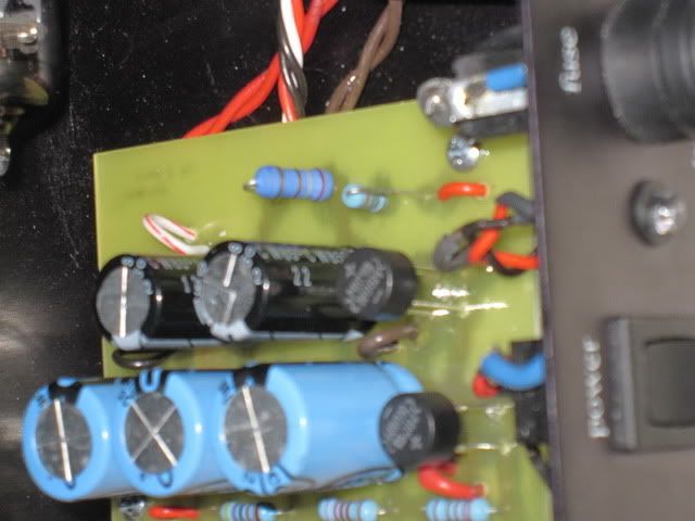
If you follow the heater wires from the power transformer they will go to the bridge rectifier module and then to the two black capacitors through the larger of the two resistors between the capacitors. Can you get the value of this resistor, as it can be changed to a slightly smaller value to get your heater voltage up a little. The smaller resistor next to it is the current limiting resistor for the power LED so we're not concerned with this one.kwm488 wrote:i haven't test the voltage of pin. but the heater DC (voltage before to go to tube) is like 5VDC. still can't arrive to 6.3VDC
It seems to be fine.kwm488 wrote:so in this movement, the PT almost 100% work and no problem?
It is 'just' a DI box, albeit one that should impart the warmth that you would get from a tube circuit rather than a solid state circuit. I wouldn't expect it to impart a massive sound of its own because that would then be a tone shaping preamp, which isn't what this unit is designed to do.kwm488 wrote:i have try this DI box once time today. compare to use with DI and direct to m audio. bass sound is more fat and deep little bit. but i don't think this expensive unit just have this function.
You may like the results and you may not. You could definitely increase the values of the power supply electrolytics which would potentially give you some overall clarity improvement by reducing the level of ripple on the power supply. If you want to change the coupling caps then you still need to fit them on the PCB and they've already chosen a variety of different types which may well have been for sonic reasons in the first place.kwm488 wrote:so if i replace all cap and resistor, i can make sure this unit is correct, right? i plan to use dale resistor. will good resistor upgrade this unit sound?
Dale RN65 resistors have a tendency to be quite warm sounding so this may be what you're looking for.
This is very difficult to do safely because you have to have the neutral wire connected to your wall socket as normal, the live wire to the black connection on your meter and the red connection on your meter to the wall socket, so that the current actually flows directly through your meter (which needs to be set to a 10A current scale before doing this).kwm488 wrote:last, should i check the current of this unit and this PT? but i don't know how to check , can you teach me.
It's dangerous because you have to assume that each of the three connections is live, and you therefore have to find a safe way to connect these. Really you want to have constructed a desktop current meter which has a socket outlet to plug into, rather than trying to rig this up on-the-fly because of the potentially fatal consequences of getting anything wrong.
I would advise against doing this because as long as you've got a small value fuse in the unit and the transformer is not getting hot, it can't be drawing enough current to worry about, and your safety is more important than having a specific number.
-
kwm488
- Senior Member
- Posts: 236
- Joined: Wed Nov 21, 2007 10:04 am
Re: question about change this demeter DI box to 220v
i think i am lucky. why? because you can do your best to help me. second is the PT not demage. demeter let me know it is $50 for the PT. it is fine to me. but i can save now.
i don't plan to do current test after listen your advice. at least, this unit is work.
but i still don't understand why? i set my muiltmeter to ac, red side of muiltmeter to one red, black side of muiltmeter to ground of pt. result is 76v, but the result of another red wire is 36v. why?
is this method wrong for ac test. but i used this method to test my marshall pt high voltage pair. 200v per wire, and pair for 400v
i think this DI box is work correct now. because i find out one record. the bass line is recorded before i connect the PT wrong. sound is almost same with now. and i turn the m audio input level lower, because it is clip. but i increase it more little, my friend told me if i just play bass louder and get clip, it is acceptable. so the different between with DI and without have more different. because i really haven't compare this DI with and without before connect wrong. i still can't 100% sure. but you are right, it is just DI. and i think it is very expensive, $599 , just make a bass note fat and warm little bit. and my friend have boss DI box, i compare it with my DI before. i remember my DI is better. so i will get it and compare again. if his DI is better to my DI, so i 100% sure my DI get some problem
if the heater not enough 6.3V, just 5V. what matter? will affact sound?
and where can i buy dale resistor? please recommend online store. partconnect don't have this item.
as the filter cap, i choose CDE 47uf/250v and BC 3300uf/25V. CDE size fit, but BC is fat little bit. these value hard to find a good brand. is this brand sound ok for me? have you try these brand cap sound?
can you help me see what value of this resistor? i think it is red, gray , gold and gold. i almost don't know how to read the metal film resistor, i jsut know how to read AB and RMG carbon film and carbon resistor.