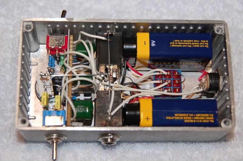
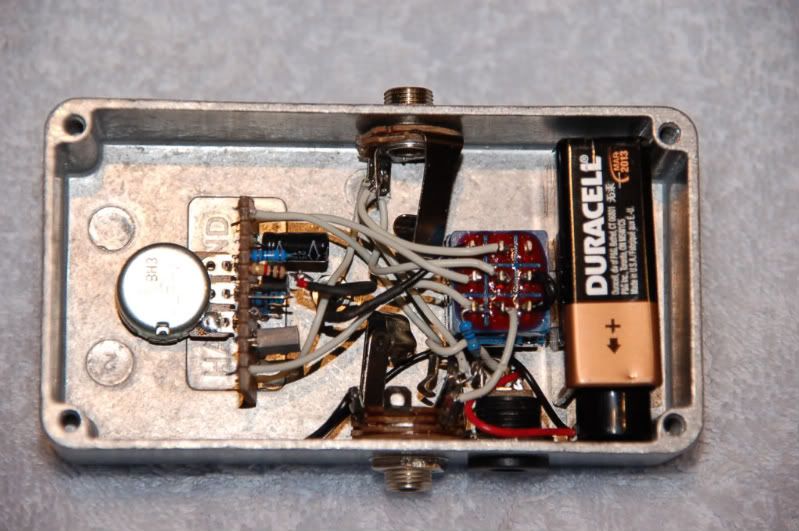
Hi Roger, it's quite a while since I last heard from you, but I guess this thread is getting old too

To answer some questions:
I use the LT1054 for the charge pump. It costs a little more but is a far more robust chip than the MAX1044. The pedal path is littered with broken MAX1044s because there was a small spike on the 9V supply

A charge pump "Doubler" will never give double the input voltage, but. if you use Schottky diodes in the charge pump circuit, you can get close to double the input voltage. A charge pump power supply is a type of switch mode or switching supply. These generate a lot of high frequency electrical noise, requiring very good filtering.
There are very few JFETs that are an exact match for the original TIS58. If I hadn't worked in R&D as assistant technician to an analog design engineer, I would probably have never understood the significance of some of the data sheet parameters. Part of my job was to find components that could meet his specifications.
It's not easy to explain the need for capacitors and resistors that go to ground, without at least a few days worth of classroom study in electronics. The simplest explanation is that an electronic circuit must have a complete path from positive to negative, or vice versa. In this circuit, ground is negative, and these components complete the path. C3 affects the frequency and phase responses of the circuit. In later versions of the EP-3 it was not in the circuit.
Spaceace, we've talked before via PM. How are you?

The true purpose of the 1M input resistor (R2) from the gate of the JFET to ground is to provide a ground reference for the gate. It's a coincidence that it also sets the input impedance, in conjunction with R1, C1 and C2. At normal guitar frequencies, the input impedance will be very close to R1+R2 = 1.1M. At radio frequencies, the input impedance will be determined by R1 and the capacitive reactance of C1. Capacitive reactance
http://www.tpub.com/neets/book2/4c.htm is the effective resistance that a capacitor will present to an AC signal. R1 and C1 create a filter to prevent radio frequencies from getting into the preamp. C1 will bleed any radio frequency signals to ground.
The output impedance is very important to the phase response of the EP-3 preamp. There's another guy selling PCBs for what he claims is the same thing as an EP-3 preamp, but he just connected a 50K pot to the end of the snippet of schematic that I posted, and that just doesn't cut it.
The Xotic EP Booster is effectively just a generic JFET Booster that has very little in common with the Echoplex EP-3 preamp. The cosmetics of the box come a lot closer to the EP-3 than the circuit inside

There are also other pedals around that use a buffer to reduce the high output impedance of the EP-3 preamp. One of the changes that came in with the EP-4 was an output buffer, and it just doesn't have the EP-3 tone.
I hope this helps.
Peter.


