Page 1 of 2
Schematic of JTM45 Custom Build
Posted: Wed Dec 16, 2009 10:51 am
by arledgsc
Hi all,
What a great forum of helpfull folks. I will be starting my Metro JTM45 kit soon and have been rounding up parts but in the meantime I created a schematic of my proposed build which may be helpful to some. Wiring diagrams are great for assembly but for me to fully understand the use of each component there is nothing like drawing a schematic and placing the parts. Gives me time to think about each and how they interact with the circuit.
This schematic notes the Larry grounding points, Lar/Mar PPIMV master volume, and Mercury PT/OT. If there are any glaring errors let me know. Some parts of the schematic were mentally converted from wiring diagrams.
Edit. VA.13. The final version after several months of tweaking. Finally nailed the sound l like. Changes include V1 byapss cap change to 25uF. Mustard caps replace the Sozos. Tone stack components adjusted to reduce bass response slightly and add some adjustment range on the bass control. PI coupling caps changed to .039uF which help blocking distortion. 100K NFB resistor which opened this amp up trememdously. No mixer bypass cap and bright cap is 100pF.
Re: Schematic of New JTM45 Build
Posted: Thu Dec 17, 2009 11:15 am
by arledgsc
The schematic above has been corrected. The 500pf bright cap/ volume pot wiring is fixed. V1 cathode cap changed from 220uF to 330uF (may reduce that later but was an error). Also B+ voltage at the first filter cap was labeled 355V dc per Mercury's spec sheet for valve rectifiers but this will probably be more around 400V dc.
Re: Schematic of New JTM45 Build
Posted: Thu Dec 17, 2009 2:12 pm
by axeman
Can you please save it and then post it on the forum, my anti virus is giving me a hard time.
Thnaks
Re: Schematic of New JTM45 Build
Posted: Thu Dec 17, 2009 2:15 pm
by jcmjmp
Sweet! Thanks!
Re: Schematic of New JTM45 Build
Posted: Fri Dec 18, 2009 8:21 am
by arledgsc
Some minor changes above. I added notation to indicate the outer foil marking orientation on Sozo vintage caps per Sozo's low impedance/ signal flow rules. Also labeled V1, V2, V3, and tone stack stages to help the beginners indentify the circuit parts mentioned in the various forum posts.
In addition in the original post I deleted the file share and added the .pdf schematic directly.
Re: Schematic of New JTM45 Build
Posted: Fri Dec 18, 2009 3:02 pm
by cagenut
Posing the inevitable question:
Any chance that you could post a layout of that for us "paint by number" guys? Please?
Re: Schematic of New JTM45 Build
Posted: Fri Dec 18, 2009 11:15 pm
by chetz
cagenut wrote:Posing the inevitable question:
Any chance that you could post a layout of that for us "paint by number" guys? Please?
+1

Re: Schematic of New JTM45 Build
Posted: Fri Dec 18, 2009 11:29 pm
by arledgsc
Any chance that you could post a layout of that for us "paint by number" guys? Please?
I'm afraid I am no help with the layout. What software package is used to put the layouts together? Our friend SDM did an outstanding job on this 50 watter. Really nice example
 http://home.comcast.net/~jbjdav26/2204PPIMVr16.jpg
Re: Schematic of JTM45 Custom Build
Posted: Sun Jun 05, 2011 3:21 pm
by LJAkaar
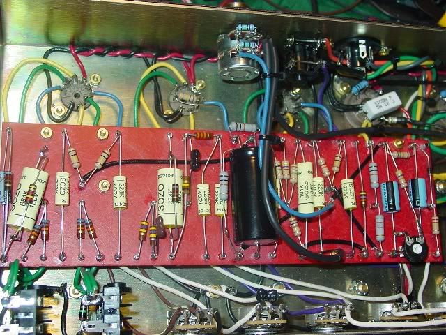
Do you have any photos of your circuit board that you could post? I'm installing hand wound Sozo caps and want to align them properly. I know enough about electricity to stay alive, but not enough to read a schematic. I hope comparing the two will help me with both problems. Thanks.
Re: Schematic of JTM45 Custom Build
Posted: Wed Jun 08, 2011 11:39 am
by arledgsc
I have an internal shot of the 50 watter with Sozo caps. Of course the JTM45 doesn't have the 0.68uF cathode bypass caps but the other caps shown have the outer foil marking band connected to the low impedance side of the circuit. The NFB pot cap is not shown but the outer foil marking is connected to GND at the NFB pot. In a Marshall amp theres some debate whether the correct connection of the cap makes any difference in the noise floor but doesn't hurt to try connect them the best way possible.
http://i30.photobucket.com/albums/c330/ ... _50W_3.jpg
The JTM45 custom schematic above is much out of date. The latest incarnation is here. Scott
http://www.keepandshare.com/doc/1619588 ... -a-18?da=y
Re: Schematic of JTM45 Custom Build
Posted: Wed Jun 08, 2011 5:59 pm
by LJAkaar
Thank you very much! This is just what I needed. The project should be done by the weekend.
Re: Schematic of JTM45 Custom Build
Posted: Sat Jun 11, 2011 3:43 am
by robert
Interesting,
but the loop is very poor, it's more or less a primitive "break jack" loop (high impedance, hi level, no return- recovery system etc.).
In no way comparable to the flexibility of the "Larry loop"

Regards
Robert
Re: Schematic of JTM45 Custom Build
Posted: Sun Jun 26, 2011 12:29 pm
by arledgsc
but the loop is very poor, it's more or less a primitive "break jack" loop (high impedance, hi level, no return- recovery system etc.). In no way comparable to the flexibility of the "Larry loop"
Well the only defense to the "poor" loop is that it does the job and has miminal effect on the original amp circuits. That is does a great job as long as you understand its advantages, weaknesses, and limits. The "poor" loop was added quickly so I could use my old TC Electronics G-Force effects on my new amps. It has worked so well I left in the design but could use a few extra dB of gain on the Return. If in the future gain control or flexibility (pedals) are needed then an outboard box (Dumbleator, C-lator, Larry Loop in a can, etc) will be added to intercept the loop signals and drive the effects. But no extra tubes or active circuits inside the amp, etc. Scott
Re: Schematic of JTM45 Custom Build
Posted: Sun Dec 16, 2012 6:22 pm
by mutts
This schematic is great but I have one question that perhaps someone can clarify. As I follow the Metroamp instructions/schematic it shows the 27K NFB resistor is connected to the 16 ohm tap of the impedance switch. However, the posted schematic shows the NFB resistor connected to the 8 ohm tap on the impedance switch. Which way is correct?? I am using the MM 045JT-16 output transformer.

Re: Schematic of JTM45 Custom Build
Posted: Mon Dec 17, 2012 1:02 am
by julkke
You can use which you like but 27k/16ohm would be "vintage correct".