Just completed my JTM45 build. I checked each connection for continuity as I went along and feel that I have good solder joints throughout (famous last words, I'm sure). I am on the initial first power-up voltage testing stage. On initial tests I have 122V AC from wall. Heater voltages were all 3.5 V AC. I assume that this is in the acceptable range.
V6 was ~5.1V AC between pins 2 & 8
Installed a NOS Mullard GZ34 and Power ON with Standby OFF position.
I am only measuring 148V DC at the Standby terminal and pins 2 & 8
I don't know where to begin to troubleshoot this. I suppose the rectifier tube could be bad, but it came from a very reputable source.
I will try to post relevant pictures.
It's been an amazing experience building this amp using all of the cumulative knowledge found in the hundreds of posts I have read on this great forum. Thanks in advance.
New JTM45 build...Voltage Issues
Moderator: VelvetGeorge
-
wharris
- New Member
- Posts: 32
- Joined: Mon May 10, 2010 11:02 pm
- Just the numbers in order: 7
New JTM45 build...Voltage Issues
- Attachments
-
- JTM 5.jpg (102.24 KiB) Viewed 2507 times
-
- JTM 4.jpg (98.91 KiB) Viewed 2505 times
-
- JTM 3.jpg (58.88 KiB) Viewed 2504 times
-
- JTM 2.jpg (85.75 KiB) Viewed 2502 times
-
- JTM 8.jpg (91.05 KiB) Viewed 2504 times
-
- JTM 7.jpg (43.1 KiB) Viewed 2504 times
-
- JTM45 1.jpg (91.7 KiB) Viewed 2504 times
-
Roe
- Senior Member
- Posts: 5056
- Joined: Thu Apr 13, 2006 1:36 pm
- Just the numbers in order: 7
- Location: Drontheim. Norwegen
- Contact:
Re: New JTM45 build...Voltage Issues
measure AC from PT (to gz34)
http://www.myspace.com/20bonesband" onclick="window.open(this.href);return false;
http://www.myspace.com/prostitutes" onclick="window.open(this.href);return false;
Super 100 amps: 1202-119 & 1202-84
JTM45 RS OT JTM50 JMP50 1959/2203/34/39
http://www.myspace.com/prostitutes" onclick="window.open(this.href);return false;
Super 100 amps: 1202-119 & 1202-84
JTM45 RS OT JTM50 JMP50 1959/2203/34/39
-
wharris
- New Member
- Posts: 32
- Joined: Mon May 10, 2010 11:02 pm
- Just the numbers in order: 7
Re: New JTM45 build...Voltage Issues
I get 327V AC @ V6 pins 4 & 6
-
Roe
- Senior Member
- Posts: 5056
- Joined: Thu Apr 13, 2006 1:36 pm
- Just the numbers in order: 7
- Location: Drontheim. Norwegen
- Contact:
Re: New JTM45 build...Voltage Issues
that seems to be right. try a different rectifier (tube)wharris wrote:I get 327V AC @ V6 pins 4 & 6
http://www.myspace.com/20bonesband" onclick="window.open(this.href);return false;
http://www.myspace.com/prostitutes" onclick="window.open(this.href);return false;
Super 100 amps: 1202-119 & 1202-84
JTM45 RS OT JTM50 JMP50 1959/2203/34/39
http://www.myspace.com/prostitutes" onclick="window.open(this.href);return false;
Super 100 amps: 1202-119 & 1202-84
JTM45 RS OT JTM50 JMP50 1959/2203/34/39
-
wharris
- New Member
- Posts: 32
- Joined: Mon May 10, 2010 11:02 pm
- Just the numbers in order: 7
Re: New JTM45 build...Voltage Issues
Thanks. I put in a new rectifier tube and everything checked out. B+ 404V. Biased tubes to 43-45. When I connected to a speaker... loud motorboating with all controls on 0. I lifted the 27k NFB...still loud motorboating with maybe a higher frequency added to the oscillations. I am thinking of adding output grid resistors. I don't plan to reverse the wires to the output grids.
Does this sound right? Any other suggestions?
Does this sound right? Any other suggestions?
-
wharris
- New Member
- Posts: 32
- Joined: Mon May 10, 2010 11:02 pm
- Just the numbers in order: 7
Re: New JTM45 build...Voltage Issues
I added the output grid resistors and all oscillations are gone. I think I have a new problem.
Input 1 sounds "normal". There is little contribution to its overall volume from "Loudness 1" and a large amount from increasing L 2. The Input 2 is pretty bright sounding, with the opposite effect from the volume knobs as described above. I have triple checked the wiring from board to pots. It is exactly like the picture in the instructions.
Input 1 sounds "normal". There is little contribution to its overall volume from "Loudness 1" and a large amount from increasing L 2. The Input 2 is pretty bright sounding, with the opposite effect from the volume knobs as described above. I have triple checked the wiring from board to pots. It is exactly like the picture in the instructions.
-
wharris
- New Member
- Posts: 32
- Joined: Mon May 10, 2010 11:02 pm
- Just the numbers in order: 7
Re: New JTM45 build...Voltage Issues
I now have a much bigger problem. Decided to retest all voltages. Numbers were all good until I slipped while measuring pin 3 @ V4. There was a spark at V5, no smoke or smell. However, after that: pin 5= -76V (was -42) V4 & 5
pin 3, 4 & 6= 64V DC (was 400, 385, 385)
I measure 347 VAC @V6 #4 and 321 VAC @V6 #6
still 5V across 2 & 8 V6
I also noticed that the VAC on V1-3 went up from 3.29 to ~3.5
Have I trashed my PT? Feeling quite dejected at this time...
pin 3, 4 & 6= 64V DC (was 400, 385, 385)
I measure 347 VAC @V6 #4 and 321 VAC @V6 #6
still 5V across 2 & 8 V6
I also noticed that the VAC on V1-3 went up from 3.29 to ~3.5
Have I trashed my PT? Feeling quite dejected at this time...
-
Roe
- Senior Member
- Posts: 5056
- Joined: Thu Apr 13, 2006 1:36 pm
- Just the numbers in order: 7
- Location: Drontheim. Norwegen
- Contact:
Re: New JTM45 build...Voltage Issues
PT is good. check rectifier tube, fuse and bias circuit
http://www.myspace.com/20bonesband" onclick="window.open(this.href);return false;
http://www.myspace.com/prostitutes" onclick="window.open(this.href);return false;
Super 100 amps: 1202-119 & 1202-84
JTM45 RS OT JTM50 JMP50 1959/2203/34/39
http://www.myspace.com/prostitutes" onclick="window.open(this.href);return false;
Super 100 amps: 1202-119 & 1202-84
JTM45 RS OT JTM50 JMP50 1959/2203/34/39
-
wharris
- New Member
- Posts: 32
- Joined: Mon May 10, 2010 11:02 pm
- Just the numbers in order: 7
Re: New JTM45 build...Voltage Issues
Thanks Roe. My 500mA fuse was blown. I am an electronic imbecile , but I am learning daily thanks to nice people like you. I appreciate you taking me under your wing on this.
My problem now is that Input 1 sounds normal (warm), Input 2 is bright. Volume 1 doesn't contribute much to Input 1 level, but Volume 2 does. In other words, If plugged into top left (High 1) Volume 1 (which sounds bright) adds minimally to overall volume, but Volume 2 (which sounds much warmer) adds most of the volume level. The opposite occurs when plugged into top right. I know that I am wired correctly according to George's instructions/pictures, but I also note that on his cartoon picture indicating the wiring of the pots, he calls the most leftward volume pot (when looking down on chassis-circuit board up-) Volume 1, when really it is Volume 2. I am not jumping inputs.
Is this the normal way that these controls should interact? My Super Lead doesn't behave in this way (Vol 2 has very little effect when plugged in to top left Input 1, and so on).
-
wharris
- New Member
- Posts: 32
- Joined: Mon May 10, 2010 11:02 pm
- Just the numbers in order: 7
Re: New JTM45 build...Voltage Issues
Has anyone else had a problem with the inputs being essentially reversed? I am sure that I wired the amp just as directed.
-
mwm523

- Senior Member
- Posts: 521
- Joined: Tue Jul 17, 2007 11:25 am
- Location: Northern NJ
Re: New JTM45 build...Voltage Issues
Trace your input and volume pot wires. I know you say that everything is wired correctly, but it sounds like you reversed something somewhere.wharris wrote:Has anyone else had a problem with the inputs being essentially reversed? I am sure that I wired the amp just as directed.
Take a look at the below, it's from the 50W kit instructions, but the inputs and volume pots are wired the same way as the JTM45:
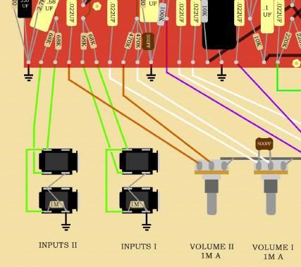
Make sure that when looking down at the board as in the pic, that:
1. the left input green wires (input II) go to the left set of 68K input resistors.
2.the right input green wires (input I) go to the right set of 68K input resistors.
3. the left volume pot (volume II) wires go to the first (leftmost) .022uf coupling capacitor and the first (leftmost) 270K (470K in the pic) mixer resistor.
4. the right volume pot (volume I) wires go to the second .022uf coupling capacitor and the second (rightmost) 270K mixer resistor.
-Mike
-
wharris
- New Member
- Posts: 32
- Joined: Mon May 10, 2010 11:02 pm
- Just the numbers in order: 7
Re: New JTM45 build...Voltage Issues
Thanks Mike. My wires go exactly as your diagram shows. The odd thing is that if you look at that same growing from the JTM45 instructions, vol 1 and vol 2 are (from L to R) labeled 1,2 even though that is not the way the pots are mounted. I assumed that the drawing was mislabeled, but that the leftmost wire would go to the first pot and so on. Looking at the photos in the directions seemed to reinforce this, but maybe I should just swap Vol 1 & 2 wires. I remain confused...
- Attachments
-
- JTM_45_KIT_V2.1.jpeg (44.96 KiB) Viewed 2239 times
-
mwm523
- Senior Member
- Posts: 521
- Joined: Tue Jul 17, 2007 11:25 am
- Location: Northern NJ
Re: New JTM45 build...Voltage Issues
Can you post some good clear pics of that area, as well as the wires going from the other side of the board to V1?
-Mike
-
wharris
- New Member
- Posts: 32
- Joined: Mon May 10, 2010 11:02 pm
- Just the numbers in order: 7
Re: New JTM45 build...Voltage Issues
Mike, your request for V1 pictures got me thinking. I checked my board and the green wires to pins 2 and 7 were reversed.  After a quick re-wire of those two everything is perfect. It sounds great, and is quiet as a mouse (Star/Larry)! And best of all, I built it with my own two grubby hands (and a lot of brain power from nice people like you). I feel fortunate to have scored one of these great kits just before the store closed down. I hope that George is able to get it up and running in the near future. Thanks for your help.
-
mwm523
- Senior Member
- Posts: 521
- Joined: Tue Jul 17, 2007 11:25 am
- Location: Northern NJ