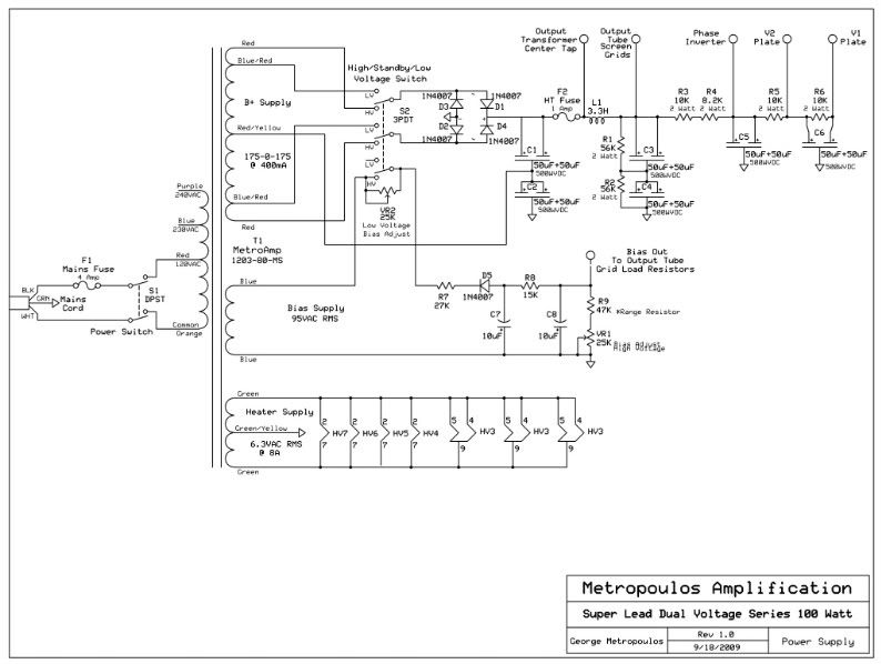
If you take a look at S2 on the schematic, you'll see that S2 is a 3P3T (3 Pole 3 "Throw", i.e "position") toggle switch. The center position is the "Off" position, so will function as the "Standby" position and break the circuit between the transformer and the rest of the power supply.
The first two poles switch the rectifier circuit between the full winding of the B+ Secondary and the blue/red wires that tap off of 80% of the secondary, which give a lower voltage.
The higher the plate voltage, the more negative the bias voltage must be. More plate voltage = more plate current, so more negative voltage is needed to limit the plate current in the tube.
Conversely, the lower the plate voltage, the less bias voltage the tube needs to keep its steady state current draw in check. Thus a resistor needs to be placed between the bias supply and the bias secondary WITHOUT breaking the circuit between the bias secondary and the bias supply so that the power tubes always have bias voltage on them even while switching between high and low voltage. This is the job of the third pole of the switch.
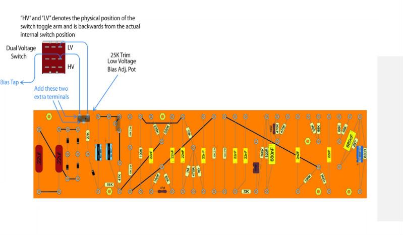
Across the common and the high voltage position of the third pole is a 25K pot. When the switch is in high voltage mode, the switch shorts the pot out, thereby taking the pot out of the circuit and making the bias supply the stock circuit.
When the switch is flipped to low voltage mode, this unshorts the pot connected to the third pole of the switch so that the resistor is now in line with the bias supply. This pot limits current flow to the bias supply from the transformer, thereby making the negative voltage at the supply output less negative. At a lower plate voltage, tubes need less negative voltage and can also draw more current than they can at high voltage. Unshorting the pot allows this to happen and allows the tubes to draw more current.
To bias a circuit with this setup -
1) With the amp in standby mode, turn on the power and measure the voltage at pin 5. Adjust both pots for the most negative voltage.
2) Once you've completed step one and the tubes are in and warmed up, flip the standby switch to the high voltage position. Set your meter to measure DC volts, connect the black lead of the meter to the chassis, and place the red lead on pin 3 of one of the output tubes.
3) Note the measurement and perform this equation -
17500 / Plate Voltage = Max Bias Current in millivolts (mV)
4) Set the meter to measure DC Millivolts (mV). Measure the voltage at pin 8. Adjust the bias control mounted on the circuit board until you get the mV reading you derived in the above equation.
5) Switch the standby switch to low voltage mode. Repeat the above steps, except for low voltage you adjust the bias with the pot that's connected to the switch.


