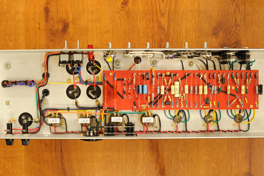
Board is in and everything's ready for the pot/control wiring, tube socket wiring and finally the board components. I have nothing soldered to the underside of the board. So, risking something coming loose is probably not going to happen. The board is also a good inch above the chassis. So I doubt I'll have a line of solder shorting to ground from a turret. The only thing I'm worried about are some of the leads already soldered around the turrets (like the choke, B+, rectifier, etc.) coming loose once I apply heat to solder a resistor or cap to a turret.
Any tips to avoid that?

