Low Power Option Standby Switch Wiring

Discuss your builds of MetroAmp Kits.

Moderator: VelvetGeorge

Post Reply
User avatar
Beavis
Senior Member
Posts: 243
Joined: Mon Jan 29, 2007 10:55 am

Low Power Option Standby Switch Wiring

Post by Beavis » Tue Jul 10, 2007 5:13 pm

Image

Is this correct?

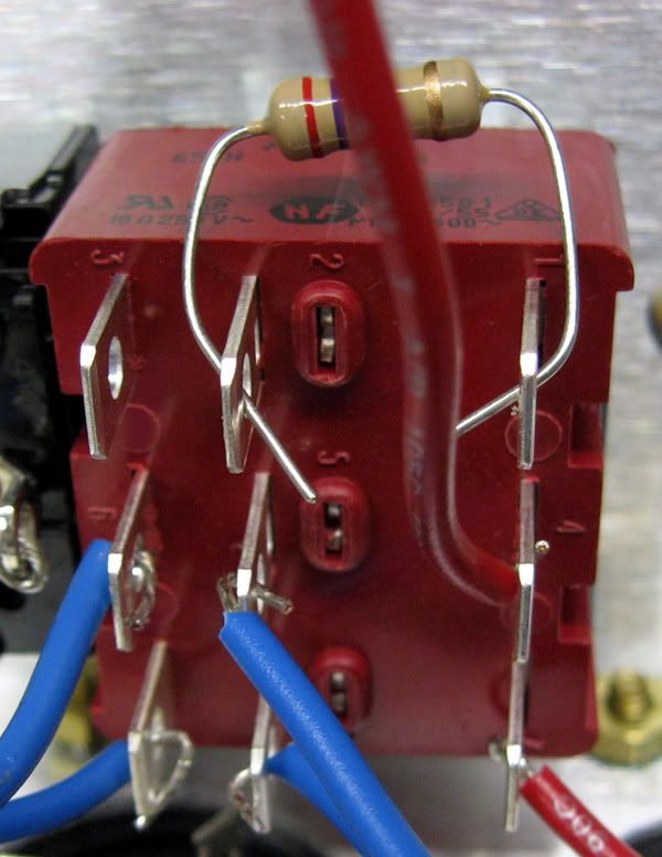
The blue wires on the left are from the OT.

I want it so the high voltage switch position is towards the power switch.

I left it out, but I believe the white bias wire will go to pin 2 of the switch.

I thought I saw a picture of this recently on the site but couldn't find it. If I recall correctly I saw a variable resistor instead of the fixed one on it. I do have two variables with my kit. Is this is for adjusting the bias separately for the two voltages?
"Humanoid's in trouble and it's scared out of its wits."

SDM
Senior Member
Posts: 1644
Joined: Sun Feb 26, 2006 6:24 am
Just the numbers in order: 13492
Location: MI

Post by SDM » Tue Jul 10, 2007 5:36 pm

http://store.metroamp.com/popup_image.p ... 58&image=2'

Can replace the resistor with a pot to fine tune the low voltage option bias setting. Also note the switch in the drawing is oriented so the toggle flips up or down rather than side to side (as your's is) to select the voltage.

User avatar
Beavis
Senior Member
Posts: 243
Joined: Mon Jan 29, 2007 10:55 am

Post by Beavis » Tue Jul 10, 2007 10:53 pm

Thanks, I think I got it now :D

I couldn't get it to fit toggling up and down.
"Humanoid's in trouble and it's scared out of its wits."

User avatar
wdelaney72
Senior Member
Posts: 1619
Joined: Sun Jan 22, 2006 9:04 pm
Location: Chicago Suburbs

Post by wdelaney72 » Wed Jul 11, 2007 8:56 am

Beavis wrote:Thanks, I think I got it now :D

I couldn't get it to fit toggling up and down.
Really? Mine's tight, but it squeeeeeezes in there.

User avatar
el34on11
Senior Member
Posts: 378
Joined: Tue Jul 18, 2006 9:30 pm
Location: Canada eh!

Post by el34on11 » Wed Jul 11, 2007 1:15 pm

So seeing the pic from the store.......The high voltage taps go to 5 &7 and the low voltage go to 6& 9 of the switch????...................Is that correct???

Thanks

Derrick
LesPauls and Marshall's

User avatar
Beavis
Senior Member
Posts: 243
Joined: Mon Jan 29, 2007 10:55 am

Post by Beavis » Wed Jul 11, 2007 1:25 pm

I think it's 4 & 7 + 6 & 9 for the hi/lo inputs to the switch.

5 & 8 go to the diodes.

This is what I think and could be wrong.
"Humanoid's in trouble and it's scared out of its wits."

User avatar
Beavis
Senior Member
Posts: 243
Joined: Mon Jan 29, 2007 10:55 am

Post by Beavis » Wed Jul 11, 2007 1:48 pm

Actually it can be 1,4,7 and 3,6,9 for the hi/lo inputs depending on how you want it to switch (Up/Down)

2,5,8 for the output to the board.

White bias wire to the free center row pin. Resistor from the free center row pin to the row with the HI voltage inputs. Then a wire from that pin to the board.

That's how I did mine. Somebody please jump in and tell me if I'm wrong. :D
"Humanoid's in trouble and it's scared out of its wits."

Post Reply