Hi, I just recieved my MV kit for my 100 watt plexi, and I was wondering in the wiki website it says to cut off the orange and green wires but it isnt to specific, could someone elaborate please? And also it would be great if I could see some pics of the mod (From beginning or the end).
Thanks
Lar/Mar PPI MV questions??
Moderator: VelvetGeorge
-
Chevelle
- Senior Member
- Posts: 83
- Joined: Sat Oct 10, 2009 2:34 pm
- Just the numbers in order: 7
- Location: Los Angeles
Re: Lar/Mar PPI MV questions??
If you already built the 100W kit, there is a green wire and orange wire that you twisted together and ran under the board from the control side to the tube side. The orange and green wire pop out under the board near V5 and V6. The orange and green wire connect to the 5.6K resistors attached to v5 and v6. Green goes to v5 and orange to v6. When you install the Larmar, one of the shielded cables (red and black wires) connets to where you previously had connected the orange and green wires on the control side of the board. The other shielded cable connects to the 5.6K resistor at v5 and v6 (the other end of the orange and green wires. Once you install the larmar, you don't need the orange and green wire. FYI - I just installed it in my 100W and it works flawlessly.
Sorry, I don't have pics.
Hope that helps.
Sorry, I don't have pics.
Hope that helps.
-
cyndicate
- New Member
- Posts: 28
- Joined: Sun Apr 04, 2010 3:50 am
- Just the numbers in order: 7
Re: Lar/Mar PPI MV questions??
Thanks for bringing up this topic! I just installed a Lar/Mar today into my new 100w superlead, never noticed I had to cut the green and orange wire. I just clipped it after reading this, are we supposed to pull those wires out after clipping them? Also did I screw anything up if I was testing out the MV with those 2 leads still hooked up?
Here's some pics of my noobie hack job (where you can still see those 2 wires connected) I took these before I read this thread so those 2 wires are gone now. So how does this look for a noobie job? I didn't build this Kit, bought it for less than what the Kit was going unbuilt so I figured I might as well grab it and build another one, will be ordering a JTM45 kit soon though.
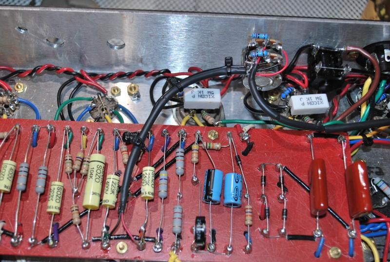
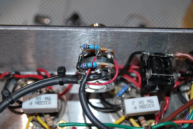
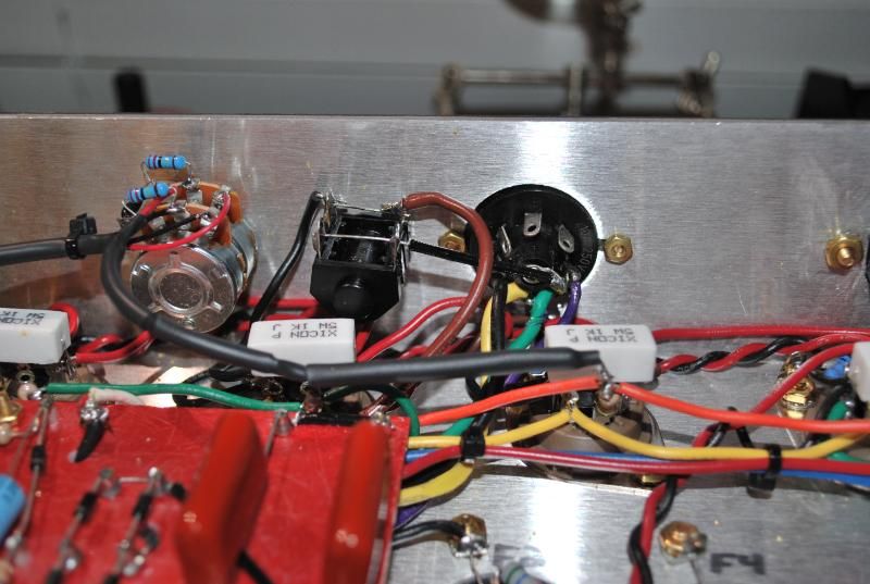
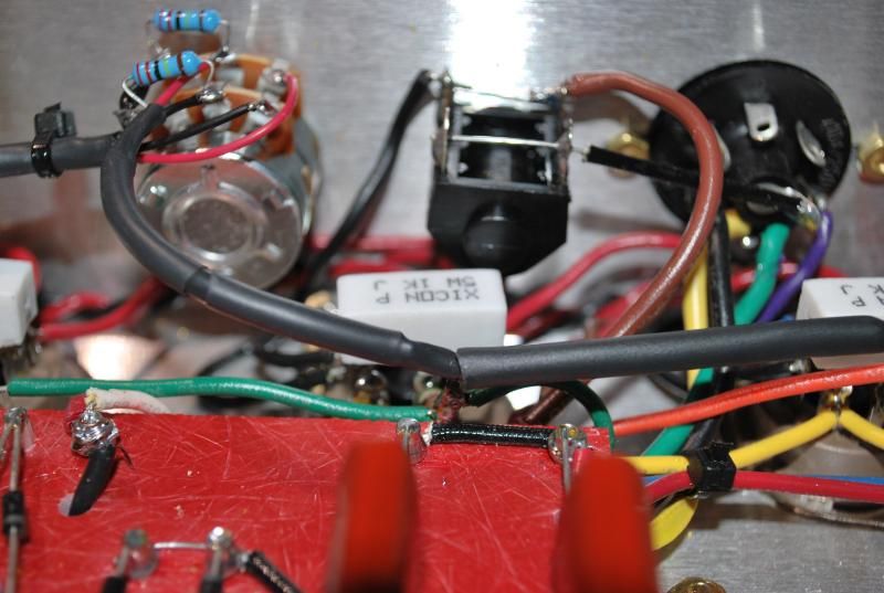
Here's some pics of my noobie hack job (where you can still see those 2 wires connected) I took these before I read this thread so those 2 wires are gone now. So how does this look for a noobie job? I didn't build this Kit, bought it for less than what the Kit was going unbuilt so I figured I might as well grab it and build another one, will be ordering a JTM45 kit soon though.
-
SDM
- Senior Member
- Posts: 1644
- Joined: Sun Feb 26, 2006 6:24 am
- Just the numbers in order: 13492
- Location: MI
Re: Lar/Mar PPI MV questions??
The orange and green wires headed from board to inner pair of power tubes (or only pair in a 50 watter) need to be removed when you install a Lar/Mar PPIMV. If those wires are left fully connected, they mess up the main intent behind the Lar/Mar as those wires each end up shorting out half a PPIMV pot section. This in turn means that as you adjust the PPIMV lower, you change the loading on the PI stages from near 220K ohms cranked, towards 0 ohms with PPIMV off. Thus PI gain is drastically effected as are roll-offs, etc.., throughout the PPIMV sweep. You will not harm the amp by accidentally leaving these wires fully connected, you just defeat the intended operation, muck up the tone you should get when using the Lar/Mar PPIMV, particularly the lower you set the PPIMV, so no worries on damage or such.cyndicate wrote:Thanks for bringing up this topic! I just installed a Lar/Mar today into my new 100w superlead, never noticed I had to cut the green and orange wire. I just clipped it after reading this, are we supposed to pull those wires out after clipping them? Also did I screw anything up if I was testing out the MV with those 2 leads still hooked up?
Gain and tone changes are the kind of thing the Lar/Mar was devised to avoid or at least minimize, and with the orange and green wires removed, as they should be, the Lar/Mar keeps the PI load more or less steady (ranges from about 220K PPIMV cranked to 250K all the way off). Since PI loading stays the same (or changes very little), PI gain stays consistent too, helping to minimize changes in tone or gain (loss of NFB, effects of how we hear/perceive lower volumes, etc.., aside).
So any way, those original orange and green wires need to go (when using a Lar/Mar PPIMV as shown installed in the usual way, like the above pics), and go completely from the amp. Don't want to leave them connected on either end as you'll basically just make two "receivers" for noise, make the amp much more prone to instability. You do not want long wires headed nowhere hanging off the power tube grids. Also, if one of them ever shorted to ground or such, you'd lose your - bias and quite possibly damage the power tubes or worse. So, just clip them near where they join the inner two power tube pin 5's (or rather the 5.6K's on them), desolder them at the other end from the two turrets on the board that they connect to. Then, just remove these two wires from the amp completely.
As to the original poster's request to see pics of the mod from beginning to end, below is a link to a step by step I drew up for someone a while back who was adding the Lar/Mar to a PCB amp. Things overall go in just the same in a turret board amp, process is the same. The last pic "be wary of the shields" was his final result and a warning to be sure that those shield wires cannot short to the pot case, as they carry the - bias supply voltage on them. Best to keep those shields shorter or heatshrink over them if any concern they may contact the PPIMV pot case. Any way, hope this helps:
http://home.comcast.net/%7Ejbjdav26/ppimvinstall.zip" onclick="window.open(this.href);return false;
-Steve
Layout site
Layout site