I recently bought the Zero Loss FX loop from Metro, and as per the instructions measured the B+ voltage to determine the necessary resistor to use. But when I measured the B+ on the 2203 I'm adding the FX loop to, I got 480V but the highest B+ listed in the instructions was 440V. I was wondering if it is safe to still add the FX loop? I calculated that I would need around a 100kOhm resistor. Is that right?
Thanks everyone.
FX Loop Questions
Moderator: VelvetGeorge
-
the hirsh

- New Member
- Posts: 14
- Joined: Fri Jul 15, 2011 9:57 pm
- Just the numbers in order: 7
-
SDM
- Senior Member
- Posts: 1644
- Joined: Sun Feb 26, 2006 6:24 am
- Just the numbers in order: 13492
- Location: MI
- Contact:
Re: FX Loop Questions
Shouldn't be that high at the PI node in a 2203. First thing to be sure of is that all the tubes are in the amp and you have it running normally before starting the loop install procedure. Need all tubes in (and thus drawing their current) to get the proper measurement at the PI node.
If not that, is this a kit/clone/home build or an original PCB amp? If the latter, could be possible you are measuring in the wrong spot if it's a latter PCB amp (pots mounted directly to board). If the former, could be the series dropping/decoupling resistors ahead of the PI in the B+ line are hooked up opposite to how the loop instructions show.
If not that, is this a kit/clone/home build or an original PCB amp? If the latter, could be possible you are measuring in the wrong spot if it's a latter PCB amp (pots mounted directly to board). If the former, could be the series dropping/decoupling resistors ahead of the PI in the B+ line are hooked up opposite to how the loop instructions show.
-
the hirsh
- New Member
- Posts: 14
- Joined: Fri Jul 15, 2011 9:57 pm
- Just the numbers in order: 7
Re: FX Loop Questions
Hey, Thanks for the help.
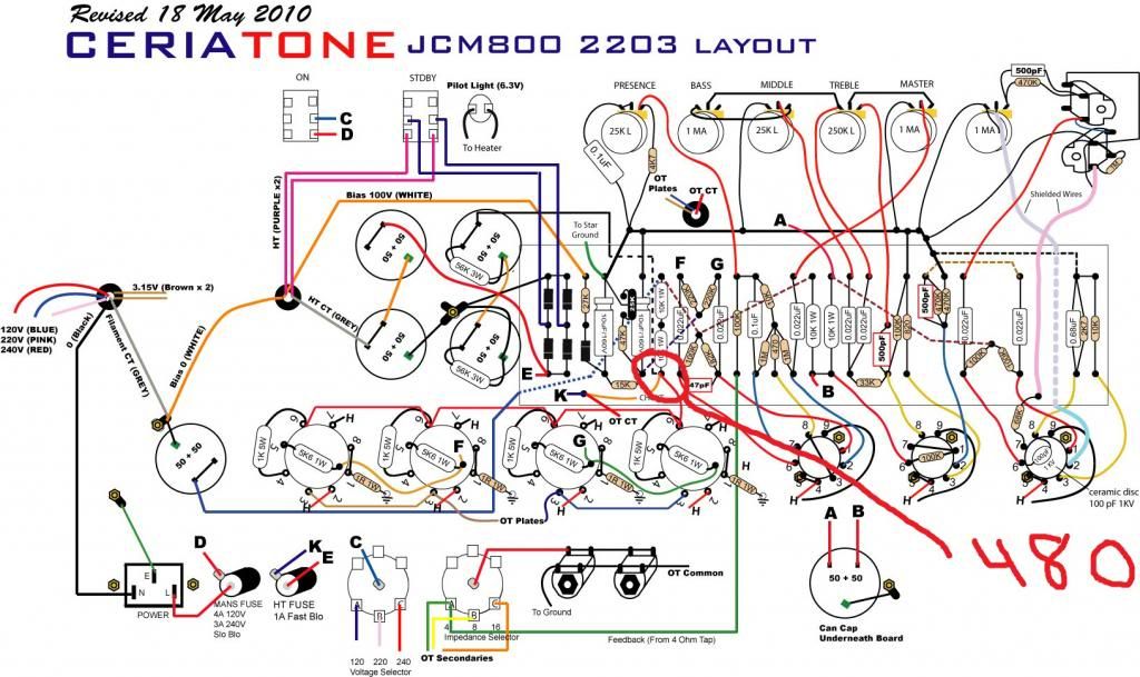
All the tubes were in the amp. Heres where I measured the voltage http://i1175.photobucket.com/albums/r63 ... iatone.jpg" onclick="window.open(this.href);return false;
The amp is a Ceriatone, built by them, and has metroamp/heyboer transformers.
Thanks
All the tubes were in the amp. Heres where I measured the voltage http://i1175.photobucket.com/albums/r63 ... iatone.jpg" onclick="window.open(this.href);return false;
The amp is a Ceriatone, built by them, and has metroamp/heyboer transformers.
Thanks
-
SDM
- Senior Member
- Posts: 1644
- Joined: Sun Feb 26, 2006 6:24 am
- Just the numbers in order: 13492
- Location: MI
- Contact:
Re: FX Loop Questions
Ah, just a case where the series dropping/decoupling resistors ahead of the PI in the B+ line are indeed hooked up opposite from usual in a 2203.
No big deal at all though, just need to measure (and later connect the loop B+ resistor to) any one of the three green circled turrets in the pic below. All 3 green circled points there are electronically the same/equivalent, all are still the PI node and all are directly connected, so just use whichever is most convenient for you. Should see around 345ish volts on them, rest of the loop instructions are the same as always from there.
No big deal at all though, just need to measure (and later connect the loop B+ resistor to) any one of the three green circled turrets in the pic below. All 3 green circled points there are electronically the same/equivalent, all are still the PI node and all are directly connected, so just use whichever is most convenient for you. Should see around 345ish volts on them, rest of the loop instructions are the same as always from there.
- Attachments
-
- measure here instead.jpg (203.2 KiB) Viewed 2117 times
-
the hirsh
- New Member
- Posts: 14
- Joined: Fri Jul 15, 2011 9:57 pm
- Just the numbers in order: 7