Hi all,
I just finished a 1969 kit and started testing the voltages.
the voltages on the tubes are very strange - with all three 12ax7s in place, no power tubes, bias set to coldest (getting -.54VDC), standby is off and I'm getting no VDC readings on the power tubes sockets, .4VDC on pin 1 of each preamp tube, .2VDC on pin 2, and 0 on pin 3.
heaters read fine on all sockets (3.1VAC).
I redressed all wires to the tube sockets to make sure the insulation isn't causing a bad connection but still nothing.
where should I start looking given the nature of the problem?
1969 SuperLead build - strange voltage readings
Moderator: VelvetGeorge
-
Elad E
- Senior Member
- Posts: 137
- Joined: Sat Jun 29, 2013 9:19 am
- Just the numbers in order: 13492
-
vh junkie
- Senior Member
- Posts: 1288
- Joined: Tue Jan 13, 2009 7:07 pm
Re: 1969 SuperLead build - strange voltage readings
If you still have the bias and heater voltages, then it sounds like the HT fuse blew right off the bat.
Keep the power tubes out til you figure out what is going on.
Check continuity (AND absence of shorts to ground) along the vDC chain from the power tubes all the way to the 100ks on v1:
Plates->choke->screens->8.2k/10k->10k->10k
Keep the power tubes out til you figure out what is going on.
Check continuity (AND absence of shorts to ground) along the vDC chain from the power tubes all the way to the 100ks on v1:
Plates->choke->screens->8.2k/10k->10k->10k
"With all due respect, sir, you're beginning to bore the hell out of me."
- Gunny Highway
- Gunny Highway
-
Elad E
- Senior Member
- Posts: 137
- Joined: Sat Jun 29, 2013 9:19 am
- Just the numbers in order: 13492
Re: 1969 SuperLead build - strange voltage readings
thanks VH Junkie,
the HT fuse was the first thing I checked - fuse is intact and passes a continuity test.
checked continuity between board component connections, board to pots and inputs and board to socket wires.
I found shorting to ground was the heater pins, which is very strange given the AC reading are in range.
I found some inconsistency on the F2-F5 cap connections' continuity so I re-flowed the solder and/or used a solder pump to renew the connections.
bottom line - still nothing, all readings are in the .1-.4VDC on all pins.
-
vh junkie
- Senior Member
- Posts: 1288
- Joined: Tue Jan 13, 2009 7:07 pm
Re: 1969 SuperLead build - strange voltage readings
Do you have the correct AC voltage(s) at the standby switch? Is the bridge rectifier wired correctly?
Check that the standby switch, diodes, mains caps and snubbers are all wired like shown here:
http://home.comcast.net/~jbjdav26/1959/ ... ubbers.JPG
Note the PT secondary center tap going to the junction of the two mains caps.
Check that the standby switch, diodes, mains caps and snubbers are all wired like shown here:
http://home.comcast.net/~jbjdav26/1959/ ... ubbers.JPG
Note the PT secondary center tap going to the junction of the two mains caps.
"With all due respect, sir, you're beginning to bore the hell out of me."
- Gunny Highway
- Gunny Highway
-
Elad E
- Senior Member
- Posts: 137
- Joined: Sat Jun 29, 2013 9:19 am
- Just the numbers in order: 13492
Re: 1969 SuperLead build - strange voltage readings
diode bridge is wired correctly.
looking at the layout in your link I can see two differences:
1. instead of the 1.5K swamp resistors between pin 5 of v4/V5 and V6/V7 in the layout I have a 5.6K resistor on each power tube's pin 5 as per Metro amps instructions.
2. in the linked layout the PT center tap is soldered to F5's negative terminal while in my amp that center tap is soldered to the same positive terminal on F4 as the snubber cap wire, again - as in the instructions by Metro amps.
beside that my amp is wired for operation in 220V so the 120V tap is wired to the pilot light which also has another wire running to the mains fuse holder.
regarding the AC on the standby switch - you mean the voltage on the PT bias taps?
-
vh junkie
- Senior Member
- Posts: 1288
- Joined: Tue Jan 13, 2009 7:07 pm
Re: 1969 SuperLead build - strange voltage readings
The (2) PT secondary voltages that feed the rectifier each go thru one half (pole) of the standby switch. You should be able to measure 350 - 400vac from ground to each half of the standby switch. After this voltage goes thru the fectifier, you need to measure it as DC. Maybe some pics would help?
"With all due respect, sir, you're beginning to bore the hell out of me."
- Gunny Highway
- Gunny Highway
-
Elad E
- Senior Member
- Posts: 137
- Joined: Sat Jun 29, 2013 9:19 am
- Just the numbers in order: 13492
Re: 1969 SuperLead build - strange voltage readings
I get 189-190 VAC on each of the B+ taps at the standby switch. are they supposed to be 400V each?
which connections make for the DC voltage test points after the diode rectifier?
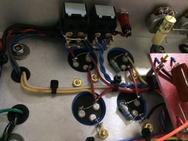
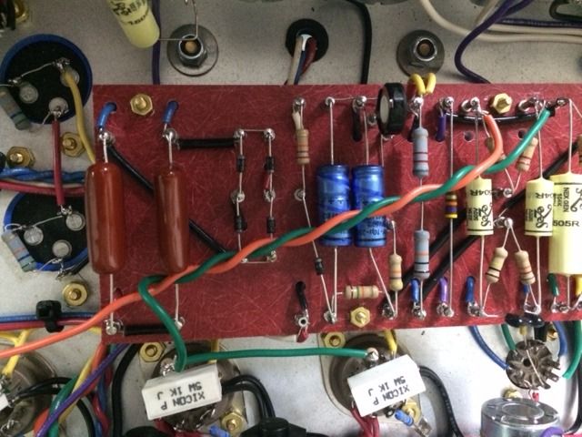
attached are a pic of the F2-F5 caps and the power/standby switches and a pic of the rectifier and bias section of the board.
the green and orange wires run above the board since I initially incorporated a LarMar PPIMV in the build and removed it when I realized troubleshooting isn't going to be a cakewalk:
which connections make for the DC voltage test points after the diode rectifier?
attached are a pic of the F2-F5 caps and the power/standby switches and a pic of the rectifier and bias section of the board.
the green and orange wires run above the board since I initially incorporated a LarMar PPIMV in the build and removed it when I realized troubleshooting isn't going to be a cakewalk:


-
vh junkie
- Senior Member
- Posts: 1288
- Joined: Tue Jan 13, 2009 7:07 pm
Re: 1969 SuperLead build - strange voltage readings
Can you post the spec sheet for the PT you are using?
"With all due respect, sir, you're beginning to bore the hell out of me."
- Gunny Highway
- Gunny Highway
-
Elad E
- Senior Member
- Posts: 137
- Joined: Sat Jun 29, 2013 9:19 am
- Just the numbers in order: 13492
-
vh junkie
- Senior Member
- Posts: 1288
- Joined: Tue Jan 13, 2009 7:07 pm
Re: 1969 SuperLead build - strange voltage readings
So... your voltage readings at the switch are correct... the black wire coming up thru the board at the left diode junction should be ground; and the red wire coming up thru the board at the right diode junction should be about 500vdc?
Then, that voltage should go to the top mains cap, and on to the HT fuseholder, then on to the turret at the bottom of the board (below the bias diode). From there, on to the OT primary CT and the choke. What OT are you using?
Then, that voltage should go to the top mains cap, and on to the HT fuseholder, then on to the turret at the bottom of the board (below the bias diode). From there, on to the OT primary CT and the choke. What OT are you using?
"With all due respect, sir, you're beginning to bore the hell out of me."
- Gunny Highway
- Gunny Highway
-
Elad E
- Senior Member
- Posts: 137
- Joined: Sat Jun 29, 2013 9:19 am
- Just the numbers in order: 13492
Re: 1969 SuperLead build - strange voltage readings
continuity to ground from the black wire junction at the diode rectifier is fine.
however, I get 0 VDC when testing for voltage at the red wire from the F5 cap.
I replaced the HT fuse just to make sure - both the new and old fuse check alright for continuity on the multi-meter and still reading zero at the right diode junction.
I'm using this ClassicTone OT:
http://www.classictone.net/40-18026.pdf
-
vh junkie
- Senior Member
- Posts: 1288
- Joined: Tue Jan 13, 2009 7:07 pm
Re: 1969 SuperLead build - strange voltage readings
Could be a bad diode... these should conduct dc in one direction but not the other... may be able to drain any charged caps and test the diodes with your meter. MIght also be a bad solder joint some where here.
"With all due respect, sir, you're beginning to bore the hell out of me."
- Gunny Highway
- Gunny Highway
-
Elad E
- Senior Member
- Posts: 137
- Joined: Sat Jun 29, 2013 9:19 am
- Just the numbers in order: 13492
Re: 1969 SuperLead build - strange voltage readings
btw, continuity test mode on the multimeter shows no shorts from the red wire at diode junction to the F5 cap, HT fuse holder and the HT red wire connection to the OT center tap and the Choke at the turret next to the bias diode.
-
Elad E
- Senior Member
- Posts: 137
- Joined: Sat Jun 29, 2013 9:19 am
- Just the numbers in order: 13492
Re: 1969 SuperLead build - strange voltage readings
hmm, I know this may sound silly but if I didn't switch the amp out of standby - why should I expect any AC to hit the rectifier bridge in the first place?
-
vh junkie
- Senior Member
- Posts: 1288
- Joined: Tue Jan 13, 2009 7:07 pm
Re: 1969 SuperLead build - strange voltage readings
Your first post suggested that standby was off ???I just finished a 1969 kit and started testing the voltages.
the voltages on the tubes are very strange - with all three 12ax7s in place, no power tubes, bias set to coldest (getting -.54VDC), standby is OFF and I'm getting no VDC readings on the power tubes sockets
"With all due respect, sir, you're beginning to bore the hell out of me."
- Gunny Highway
- Gunny Highway