Page 2 of 5
Re: Help with my JTM100 1203-80 layout
Posted: Tue Mar 20, 2012 5:27 pm
by Homebelly
Okay..
How about this..?
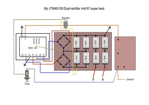 Rectifier and filter board-2
 by
Homebelly
I've been trying to work it all out using the schems linked to above.
I'm still not sure about where #3 and #4 goes

Re: Help with my JTM100 1203-80 layout
Posted: Tue Mar 20, 2012 8:03 pm
by Kevin
Hey Charlie,
Green wire (heater center-tap) should go to ground, not between the mains caps.
Yes, that orange "Choke?" wire should go to the choke. Another wire from this point should go to the OT.
3 should go to a screen grid resistor on a power tube socket (they are all connected).
4 should go on the bottom end (pot side) of the voltage dropping resistor for V3/PI (big one beside the bias supply).
Are you going with the dual-rectifier setup? My recommendation is to wire it up as a single primary with centre-tap, leaving the bottom diamond in place for looks. Depends what tones you're after... Maybe Roe and Neil will chime in on this point.
Are you going with Larry grounding? If so, the grounds have to be broken up.
Re: Help with my JTM100 1203-80 layout
Posted: Tue Mar 20, 2012 8:12 pm
by Homebelly
Kevin wrote:Hey Charlie,
Green wire (heater center-tap) should go to ground, not between the mains caps.
Yes, that orange "Choke?" wire should go to the choke. Another wire from this point should go to the OT.
Are you going with Larry grounding?
Hi Kevin.. good to see you up in my build thread

I got a thread running on the mastran forum and Brian just posted.. these are his tips..
 Rectifier and filter board.3
 by
Homebelly
And yes.. i'll be going with Larry's grounding scheme.
I'll work up a drawing for that after i have this all figured out.
Re: Help with my JTM100 1203-80 layout
Posted: Tue Mar 20, 2012 8:15 pm
by Kevin
Edited my post after your response.
Re: Help with my JTM100 1203-80 layout
Posted: Tue Mar 20, 2012 8:27 pm
by Homebelly
Kevin wrote:Edited my post after your response.
Cheers Kevin..


I'm planning on using the dual rec for the actual build, then maybe try the amp with a single rec later down the line.
I must also add that i am loving the detective work involved in this, i must have every picture of every dual rec Marshall that is available on the interwebz on my hard drive, along with as many schem's as i can find. Its all equal parts revealing and confusing

Re: Help with my JTM100 1203-80 layout
Posted: Wed Mar 21, 2012 8:19 am
by Roe
Homebelly wrote:Kevin wrote:Hey Charlie,
Green wire (heater center-tap) should go to ground, not between the mains caps.
Yes, that orange "Choke?" wire should go to the choke. Another wire from this point should go to the OT.
Are you going with Larry grounding?
Hi Kevin.. good to see you up in my build thread
I got a thread running on the mastran forum and Brian just posted.. these are his tips..
Rectifier and filter board.3 by
Homebelly
And yes.. i'll be going with Larry's grounding scheme.
I'll work up a drawing for that after i have this all figured out.
Its starting to look good - and yes the larry grounding is worth looking into
Re: Help with my JTM100 1203-80 layout
Posted: Wed Mar 21, 2012 7:06 pm
by emmjaydubya
Wow fantastic thread, thanks guys!
Re: Help with my JTM100 1203-80 layout
Posted: Thu Mar 22, 2012 3:05 am
by Homebelly
emmjaydubya wrote:Wow fantastic thread, thanks guys!
You welcome..
Its nice to be getting all of the great feed back from the different builders up in the joint, and also finally be able to give something back after my three years of being a member, and my previous year or so of being a lurker and sucking up all of the great knowledge available here.

I should be able to post a couple more sketches early or mid next week.
Re: Help with my JTM100 1203-80 layout
Posted: Thu Mar 22, 2012 7:42 pm
by Homebelly
Kevin wrote:
3 should go to a screen grid resistor on a power tube socket (they are all connected).
4 should go on the bottom end (pot side) of the voltage dropping resistor for V3/PI (big one beside the bias supply).
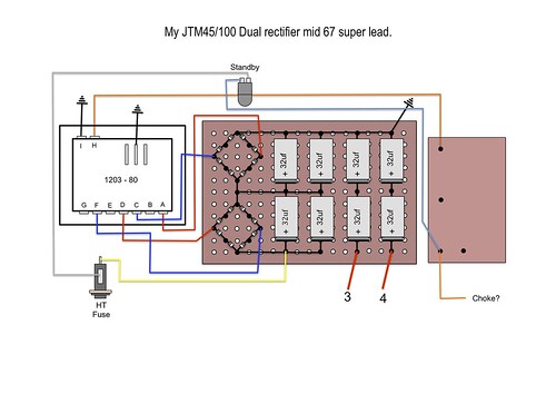
How is this?
 Final filter cap hookup
 by
Homebelly, on Flickr
Re: Help with my JTM100 1203-80 layout
Posted: Fri Mar 23, 2012 12:18 am
by Homebelly
Okay..
And here is the out-put transformer, can some one let me know if this is all good?
I think it's pretty straightforward, but just want confirmation.
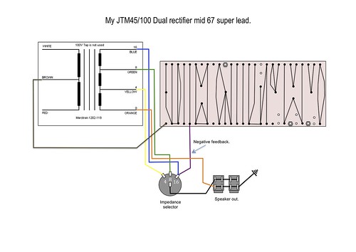 Out-Put transformer impedence and speakers
 by
Homebelly, on Flickr
Cheers.
Re: Help with my JTM100 1203-80 layout
Posted: Fri Mar 23, 2012 2:19 am
by Homebelly
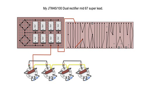
And one more.
This one showing the secondaries, the choke and the Grid stoppers.
 Out-Put transformer and choke
 by
Homebelly
Once again.. feed back welcomed.
But again, i think this is pretty straight forward.
Re: Help with my JTM100 1203-80 layout
Posted: Fri Mar 23, 2012 3:46 am
by neikeel
Hi, back again!
Yes looks fine to me (assuming all your colours are correct for the trannies you are using!)
Re: Help with my JTM100 1203-80 layout
Posted: Fri Mar 23, 2012 8:05 am
by shakti
Check your screens and PI filtering layout again...it's messed up.
Re: Help with my JTM100 1203-80 layout
Posted: Fri Mar 23, 2012 12:30 pm
by neikeel
Ah - I only checked the OT diagram bit!
You need to take the HT feed (after the choke) to the turret where the wire is hooked up now (one end of the 8k2 dropper) and take a yellow wire from that turret to your screens.
The other end of the 8k2 dropper should have that short red feed wire (to teh PI plates) which should then be hooked up to the PI filter cap and then on through the bus wires into the preamp.
Re: Help with my JTM100 1203-80 layout
Posted: Fri Mar 23, 2012 11:25 pm
by Homebelly
I'm not in good shape today i must admit.

Nasty migraine, so i'm not running on all cylinders.
Probably not the best state of mind to be in while looking at this sort of stuff, but can some one confirm I have this diagram correct..
Homebelly wrote:Kevin wrote:
3 should go to a screen grid resistor on a power tube socket (they are all connected).
4 should go on the bottom end (pot side) of the voltage dropping resistor for V3/PI (big one beside the bias supply).
How is this?
Final filter cap hookup by
Homebelly, on Flickr