C = M = "C"lone
Hendrix's tubes
Moderators: VelvetGeorge, BUG
-
JimiJames

- Senior Member
- Posts: 3550
- Joined: Fri Dec 23, 2005 6:32 pm
- Just the numbers in order: 13492
- Location: Chicago
- Contact:
Re: Hendrix's tubes
daveweyer Thanks for shedding light on why Celestion has stated that they didn't know exactly what was used in his Big Bottom's and when Marshall re-issued the cabinet, Celestion just labelled them "C" = G12-C.
C = M = "C"lone
C = M = "C"lone
-
spaceace76

- Senior Member
- Posts: 1673
- Joined: Sat May 10, 2008 11:54 am
- Just the numbers in order: 7
Re: Hendrix's tubes
can you elaborate on this? what sort of compression is introduced? that sounds like it would change the response of the amp quite a bit, not in a bad way but certainly differentdaveweyer wrote:When the amp is in hard clipping mode, the screen current can rise by a factor of ten because the screen is trying to do the work of the plate; the 2K resistors cause a substantial drop in the screen voltage whenever the instantaneous plate voltage is below the screen voltage. This limits total output power of the circuit, but it saves the screens, and the output tubes, and also gives a very nice sort of compression, like power supply sag (which Neil Young loved and called "sucking").
-
Roe
- Senior Member
- Posts: 5056
- Joined: Thu Apr 13, 2006 1:36 pm
- Just the numbers in order: 7
- Location: Drontheim. Norwegen
- Contact:
Re: Hendrix's tubes
bigger screen resistors gives a softer attack but it works well on high voltage amps (these amps typically have a faster attack than low voltage amps anyway)
http://www.myspace.com/20bonesband" onclick="window.open(this.href);return false;
http://www.myspace.com/prostitutes" onclick="window.open(this.href);return false;
Super 100 amps: 1202-119 & 1202-84
JTM45 RS OT JTM50 JMP50 1959/2203/34/39
http://www.myspace.com/prostitutes" onclick="window.open(this.href);return false;
Super 100 amps: 1202-119 & 1202-84
JTM45 RS OT JTM50 JMP50 1959/2203/34/39
-
daveweyer
- Senior Member
- Posts: 713
- Joined: Wed Oct 29, 2014 9:36 pm
- Just the numbers in order: 13492
Re: Hendrix's tubes
That's right, since there is extra power anyway, the response change is really only noticeable compared to a high voltage amp with the stock resistors. For some players, this slightly diminished attack is actually better. I've had guys tell me they didn't notice the difference after the mod, but I could usually feel it.
I like the powerful attack, but it's not worth sacrificing the tubes for in a high voltage amp. And remember, some of the amps which showed up at West Coast Organ and Amp had plate voltages of 650 volts; those were the ones with the Drake PTs that were wound for 110 volts on the primary, supposedly a design mistake, but ending up in a whole batch of Marshalls. The screens just couldn't take that much voltage (power actually) during heavy use and just melted.
I even had some EL34s where the glass melted.
The 2K2 screen resistors were just a very quick fix, not a real solution.
-
Jazz
- New Member
- Posts: 8
- Joined: Sat Mar 12, 2016 2:28 pm
- Just the numbers in order: 13492
- Location: Eastern Europe
Re: Hendrix's tubes
Hi Davedaveweyer wrote:Plates and screens. There are two basic ways to deal with over-dissipation of screens, and one very simple idea is to limit the screen current by using a 2K 10 watt resistor on each screen, something I did on several of Jimi Hendrix' amps.
When the amp is in hard clipping mode, the screen current can rise by a factor of ten because the screen is trying to do the work of the plate; the 2K resistors cause a substantial drop in the screen voltage whenever the instantaneous plate voltage is below the screen voltage. This limits total output power of the circuit, but it saves the screens, and the output tubes, and also gives a very nice sort of compression, like power supply sag (which Neil Young loved and called "sucking").
The second way to control screen current is to use separate supplies, or a regulator similar to what Guild used on their Quantum amps with 8417 output tubes; their circuit used a 6GF7 series regulator which essentially provided 300 volts to the screens at any output operating level, and allowed them to use 560 volts on the plates of the output tubes without having to worry about over-dissipation of the screens. They could actually get 100 watts from this design using only two tubes, and count on good longevity.
When I received Jimi Hendrix' Guild Quantum amp for repair in 1968, the transformer was blown, but the output tubes were still okay; I was surprised and remembered the circuit as being special.
You can also use shunt regulation to keep the screen voltage at a predetermined level, the system wastes heat, but is extremely fast and quite simple to implement. Essentially, the circuit uses a device, like a large Zener, or zener/transistor combo to substitute for the the maximum current draw of the screens, meaning there is substantial heat generated when the amp is at idle. It's really a dummy load that draws current through a dropping resistor, when the screens begin to draw current the dummy load drops out of the picture gradually until the screens are drawing all the current in the dropping resistor. This holds the screens at a constant voltage within the operating range.
I installed one of these circuits in one of Jimi's Marshalls, and I think it worked out pretty well. Somebody somewhere has this Marshall if it didn't get trashed and probably wonders what the strange circuit is all about.
In the 1950s the "ultra-linear" circuits became very popular in the Hi-Fi world, and the KT and EL series of output tubes were targeted for these circuits, one notable feature of which was the plate and screen working at the same voltage, both connected to taps on the output transformer. When you check the plate voltage on these amp designs you will see it maintained in the more comfortable 400 volt range, precisely for longevity of the output tubes.
These amps were never intended to operate in hard clipping either, which is something the designers of guitar amps didn't think that much about when they basically copied these designs and simply raised the plate voltages and currents to get the desired output power.
I'll deal with specific mods and the storied "Governor" amp which originated at West Coast Organ and Amp Service, in a future post.
DW
What do you think about this simple solution to get optimum and safe value of screen grids voltages for let`s say standard quartet of EL34 power tubes pentode connected , where relative stable and `clean` screen grids supply voltage is obtained via filter choke from main transformer secondary center tap ? , I think in this way we can get in the same time both high output power and power tubes longevity .
http://imageshack.com/a/img923/6643/gaUSei.jpg
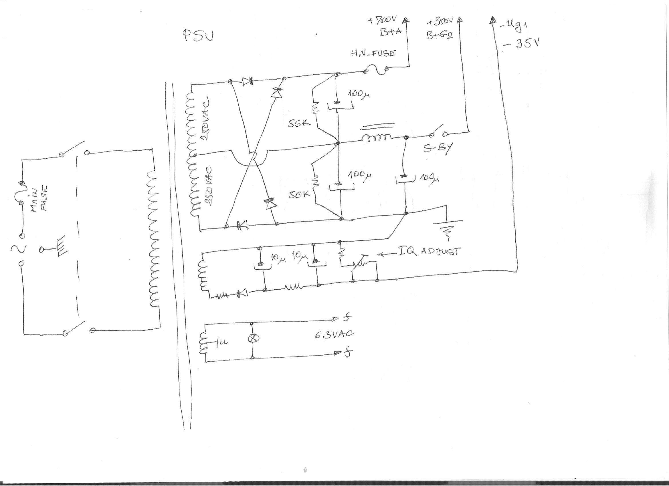
http://imageshack.com/a/img921/2209/wWAHP5.jpg
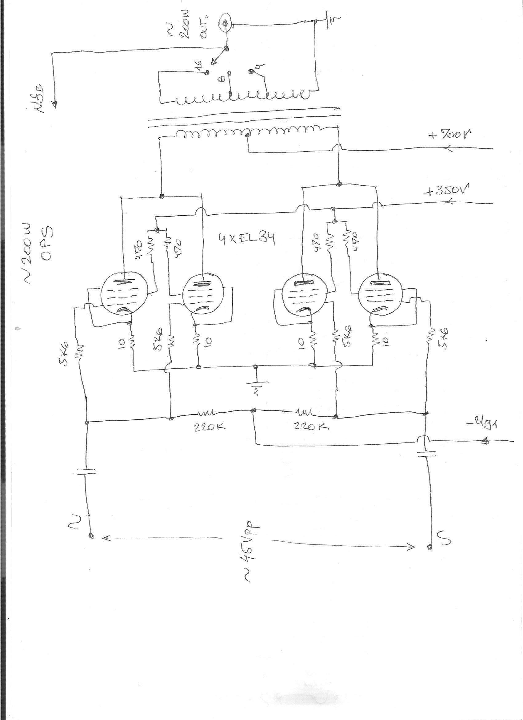
Best Regards
Blast from the past...