RECTIFIER VOLTAGE PROBLEM on a JTM45 RI with HW board ?
Moderator: VelvetGeorge
-
electricskychurch
- Senior Member
- Posts: 968
- Joined: Fri Apr 22, 2005 9:08 pm
- Location: france
-
electricskychurch
- Senior Member
- Posts: 968
- Joined: Fri Apr 22, 2005 9:08 pm
- Location: france
-
electricskychurch
- Senior Member
- Posts: 968
- Joined: Fri Apr 22, 2005 9:08 pm
- Location: france
-
electricskychurch
- Senior Member
- Posts: 968
- Joined: Fri Apr 22, 2005 9:08 pm
- Location: france
in step 12 of the jtm45 amp kit guide : "wiring the output tubes grids, bias ..." georges speaks about a yellow wire to solder on one lug of the 16 uf cap and a white wire to the rectifier.
where do those yellow and white wires come from (knowing the colors in my jtm45 ri are different !) ?
on pin 6 of the rectifier, there was only one wire coming from the PT (as on pin 4, both red wires for 300VAC )
i suppose the yellow is coming from the 10K resistor closest to the preamp circuit (in contact with v2 pin 6)
another thing i don't understand is why georges has a dual 32 uf & a dual 16 uf on the chassis as well as another 16uf on the board.
on the PTP board guide it says he left the two dual caps outside for the jtm45 ri but doesn't talk about the single 16uf from his amp kit
-
Flames1950

- Senior Member
- Posts: 9294
- Joined: Sun Feb 08, 2004 1:04 am
- Location: Waukee, Iowa
I just put one of those Marstrans in Steve's (bluze81's) JTM45 build and I'm pretty sure that the red goes to the power tube closest to the preamp tubes, and the black to the power tube closest to the rectifier. Yes, if those are switched you will show a huge bias current draw, as well as some nasty hum if you're plugged into a speaker cab (what are you using for a load?)electricskychurch wrote:is the start of the primary OT ( black on marstran 103) the wire going to the power tube next to V3 (PI) and the finish (red on the marstran 103 ) going on power tube closest to rectifier ?
originaly on the drake OT they were RED to V4 and WHITE to V5 .
CENTER TAP wax BLACK on drake OT and is brown on marstran 103.
anyway i'm not sure a reverse secondary OT would blow muy HT FUSE and lower my high voltages on power tubes .
Try lifting one end of the 27K feedback resistor (the one with a purple wire at each end, one going to the impedance selector and the other to the presence control) and see if your bias readings are back where they should be. If that seems to correct the problem then swap the red and black wires from the output tranny.

-
electricskychurch
- Senior Member
- Posts: 968
- Joined: Fri Apr 22, 2005 9:08 pm
- Location: france
take a look on marstan.com for the OT wirings (as well as the 93 jtm45 ri shematics ).
for the jtm45w /100v (103 OT) it shows from top to bottom :
BLK (START)
BRN
RED/FINISH
i suppose i can compare this wiring to the ones on the schems and they are reversed
i don't think i reversed but i will try what you say and will see.
maybe i'm wrong but i don't think i reversed.
on my amp the black goes v4 and red v5 ( brown center tap to 32uf cap), on jtm45 ri schem it's red at the top to v4 and white at the bottom to v5.
-
electricskychurch
- Senior Member
- Posts: 968
- Joined: Fri Apr 22, 2005 9:08 pm
- Location: france
-
Flames1950
- Senior Member
- Posts: 9294
- Joined: Sun Feb 08, 2004 1:04 am
- Location: Waukee, Iowa
Well I'm on the wrong computer to dig up pics of Steve's amp (and he wanted to unveil it at some point himself) but I started out with the same reasoning, that "start" would be the tube closest to the preamp tubes and "finish" would be next to the rectifier. And I had to swap them when I tested the amp. Nowhere on Brian's site does it say that "start" corresponds to the tube closest to the preamp tubes, it's just an assumption we all make.....and a wrong one at that. Or else Heyboer switched the leads on this run of trannies, which has happened with some of George's trannies at different times too.
-
electricskychurch
- Senior Member
- Posts: 968
- Joined: Fri Apr 22, 2005 9:08 pm
- Location: france
i unsoldered one side of the feedback resistor and i now read 32mv (32ma), so it seems you're right !!! yeeeeessss!!!
i must be dumb cause when i compare the 103 OT wiring diagrams and the shems i still don't see my mistake !
i will reverse the secondary OT and check again.
if i had plugged it in a cab i would have heard the motor boating or osscillation noise but i was plugged on the dummy load of my THD hotplate (load mode, no sound !!) .
i will try .
thanks for the tip, i will verify all that now.
btw, i have a 65' jtm100 super pa all drake trannies (3" PT) and kt66, do you know if the dickinson 33k/500 pf was really made during hendrix life, in 66 or 67; i read jim marshall saying hendrix never asked for any mod, just for a support anywhere in the world.
i feel the sound is thinner with that mode.
-
electricskychurch
- Senior Member
- Posts: 968
- Joined: Fri Apr 22, 2005 9:08 pm
- Location: france
ok, i see you made the same experience as i do.
i just plugged the amp in a cab with feedback resistor soldered back and had this crazy boat siren sound, so i suppose you were right.
thanks very much cause i went through this OT wiring several times but wasn't sure i was wired correctly though i interpreted the diagram that way.
i didn't know it would make the bias reacting like that and loose some voltage .
-
Flames1950
- Senior Member
- Posts: 9294
- Joined: Sun Feb 08, 2004 1:04 am
- Location: Waukee, Iowa
I scared the hell out of my wife when I plugged Steve's amp in -- I was pretty sure the leads were reversed from my bias readings but I knew the speaker wouldn't lie -- she came barreling down the stairs, I think she thought I'd just killed myself!!!!electricskychurch wrote:ok, i see you made the same experience as i do.
i just plugged the amp in a cab with feedback resistor soldered back and had this crazy boat siren sound, so i suppose you were right.
thanks very much cause i went through this OT wiring several times but wasn't sure i was wired correctly though i interpreted the diagram that way.
i didn't know it would make the bias reacting like that and loose some voltage .
-
electricskychurch
- Senior Member
- Posts: 968
- Joined: Fri Apr 22, 2005 9:08 pm
- Location: france
-
electricskychurch
- Senior Member
- Posts: 968
- Joined: Fri Apr 22, 2005 9:08 pm
- Location: france
-
Flames1950
- Senior Member
- Posts: 9294
- Joined: Sun Feb 08, 2004 1:04 am
- Location: Waukee, Iowa
Actually, now that I'm on the computer with the pictures, NO.......Steve's amp when finished had the black to the preamp side power tube and the red to the rectifier side power tube. But yours shows bias symptoms of the opposite wiring being correct, and again, Heyboer's been known to swap these things around without warning........
But you shouldn't blow either fuse from the output tranny wires being backwards in any case. Something else is wrong here, and we need to nail it down so we can be sure of which way your output tranny needs to be wired.
I'll flash a pic of Steve's finished amp and hope he's not too upset, although the way I bundled the wires with lacing may not be of much help to you........
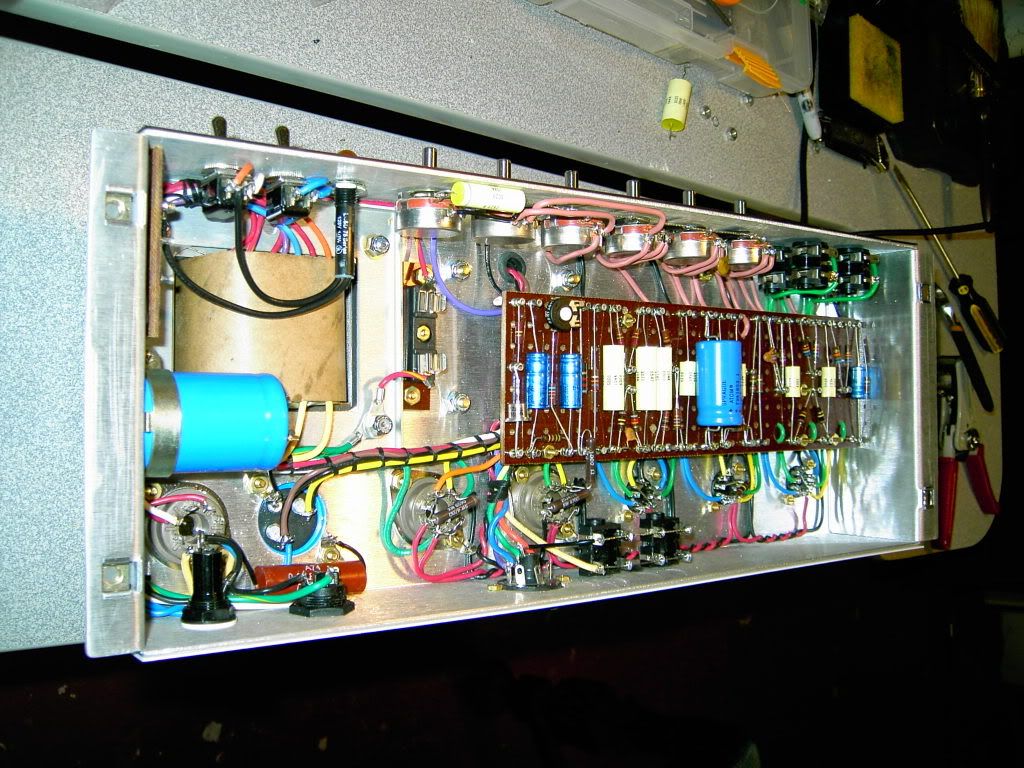