Hi there guys!
I'm new here... first post. so, take it easy if I'm giving you dumb questions.
Well, I got a amp (single-ended 6l6 based) with a two 12ax7s preamp section. Last week I decided to give it more options of different tones and gain. So I decided to install a DPDT switch (on-on) so that I can choose between different capacitors and resistors in the first triode of second preamp's tube.
I did it, but what I got now is a loud "pop" when changing the switch position, either way...
I'm attaching a image which describes the schematic and the layout I build for this sector.
Does anyone here know how I can get rid of this noise?
Thanks!
Cathode capacitor switch schematic
-
viniciusvalenca

- New Member
- Posts: 14
- Joined: Sun Apr 12, 2015 5:28 pm
- Just the numbers in order: 13492
Cathode capacitor switch schematic
- Attachments
-
- esquema-ingles.jpg (56.29 KiB) Viewed 1829 times
-
Haze13
- Senior Member
- Posts: 413
- Joined: Tue Oct 16, 2012 10:33 am
- Just the numbers in order: 13492
- Location: Israel. Bat-Yam
Re: Cathode capacitor switch schematic
Things like these are done with switching circuits based on jfets - flip flop of the boss/ibanez stomp boxes. ADA pre-amps used some thing similar, I think (may be I'm wrong). Carvin used a switch there, very similar to what you did, but not exactly... It worked and it was silent. Look for the X100b schematic.
-
Carbia

- Senior Member
- Posts: 383
- Joined: Sun Jul 05, 2009 1:34 pm
- Just the numbers in order: 7
- Location: Spain
Re: Cathode capacitor switch schematic
You don't need fet switching to avoid pops... just use a pull down resistors and never leave the cathode open.
I made a paint to show you how it is... don't laugh at me for the painting...
You don't need a DPDT, a DPST it's fine to do it, but you can wire the DPDT as a DPst easily.
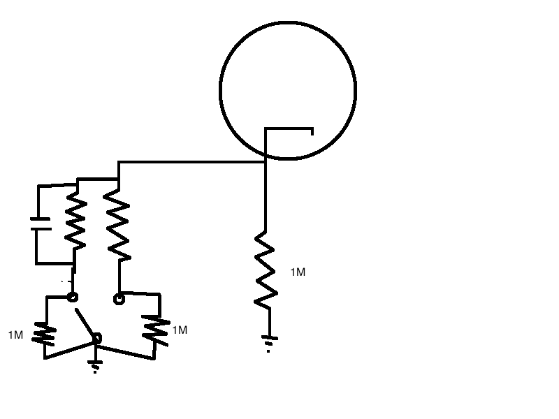
You can use 2M2 resistors. Try the best combination and it shouldn't make noise.
I made a paint to show you how it is... don't laugh at me for the painting...
You don't need a DPDT, a DPST it's fine to do it, but you can wire the DPDT as a DPst easily.

You can use 2M2 resistors. Try the best combination and it shouldn't make noise.
-
viniciusvalenca
- New Member
- Posts: 14
- Joined: Sun Apr 12, 2015 5:28 pm
- Just the numbers in order: 13492
Re: Cathode capacitor switch schematic
Thanks for the input, guys!
Carbia, do the resistors must be value matched? I don't have matched value resistors for 1M neither 2M2 for now...
I did what you suggested, but instead of using 1M or 2M2, I used one 470k and 1M5.. the pop is still there
According to your schematic, I see a 1M connecting the pin 8 to ground. Is that really needed? Could it be another value? As far as I'm concerned that resistor will be connect in parallel to pulldown 1M resistors by switching posistions.. it would give 500k resistance... too much for a cathode?
-
Carbia
- Senior Member
- Posts: 383
- Joined: Sun Jul 05, 2009 1:34 pm
- Just the numbers in order: 7
- Location: Spain
Re: Cathode capacitor switch schematic
Yes, you need the resistor going from pin 8 to ground, because if there's not, there's a time in which the cathode has no ground reference.
The values really doesn't matter so much.
The pull-down resistors are in parallel when that branch are not engaged, so it's no noticeable the effect.
And the 1M cathode resistor is bypassed by the Resistor/capacitor engaged, so 1k5 in parallel with 1M is something very close to 1k5...
Another thing you can do to to it in a easier way, is just paralleling a capacitor.
I mean: put a 1k5 cathode resistor and just engage/disengage a cap in parallel with a DPST. in the engaged position, connect the cap to ground, and in the other position, connect it to a 470k or higher resistor going to ground.
-
viniciusvalenca
- New Member
- Posts: 14
- Joined: Sun Apr 12, 2015 5:28 pm
- Just the numbers in order: 13492
Re: Cathode capacitor switch schematic
Do you think it's very critical having all the pulldown resistors value matched?
Couse.. as I said, I did it but using different values... the pop is there still.
Tomorrow I'll try to do what you suggested later... just engaging/disengaging the capacitor. A fixed value for the cathode resistor.
Thanks!
Couse.. as I said, I did it but using different values... the pop is there still.
Tomorrow I'll try to do what you suggested later... just engaging/disengaging the capacitor. A fixed value for the cathode resistor.
Thanks!
-
Carbia
- Senior Member
- Posts: 383
- Joined: Sun Jul 05, 2009 1:34 pm
- Just the numbers in order: 7
- Location: Spain
Re: Cathode capacitor switch schematic
Just try and try...
Popping issues are complicated sometimes, but, it can be done, sure.
Popping issues are complicated sometimes, but, it can be done, sure.
-
white noise

- Senior Member
- Posts: 262
- Joined: Sat Jun 22, 2013 9:09 am
- Just the numbers in order: 13492
- Location: San Antonio Texas
Re: Cathode capacitor switch schematic
Try this:

-
d95err
- New Member
- Posts: 31
- Joined: Tue Nov 08, 2011 3:28 am
- Just the numbers in order: 7
Re: Cathode capacitor switch schematic
No, they don't need to be matched. Any value from about 100k to a few Megs will be fine, and it doesn't matter if they have the same value or not.viniciusvalenca wrote:Do you think it's very critical having all the pulldown resistors value matched?
-
viniciusvalenca
- New Member
- Posts: 14
- Joined: Sun Apr 12, 2015 5:28 pm
- Just the numbers in order: 13492
Re: Cathode capacitor switch schematic
Hi guys!
Thanks for the inputs!
Today I did some mods in the circuit. Instead of using just a fixed resistor (1k5) connecting the cathode to ground, I put a 1uF cap in parallel with it, leaving the dpdt the purpose of switching in and out a 22uF cap (FAT position). That annoying pop disappeared...
But the tone difference between both positions is quite subtle.I'm not sure if it's due the fact I'm using just a telecaster to test (a tele has lack of lows usually, this one I'm using, particularly) or the 1uF is already giving quite the same gain boost the 22uF would give itself.
Any thoughts?
-
Carbia
- Senior Member
- Posts: 383
- Joined: Sun Jul 05, 2009 1:34 pm
- Just the numbers in order: 7
- Location: Spain
Re: Cathode capacitor switch schematic
with a larger resistor, the capacitor effect is more obvious.
Try 2k7 or higher
Try 2k7 or higher
-
viniciusvalenca
- New Member
- Posts: 14
- Joined: Sun Apr 12, 2015 5:28 pm
- Just the numbers in order: 13492
Re: Cathode capacitor switch schematic
Well, fellows...
I took part of the suggestion from white noise and combined to what Carbia did... I think I got there!
Firstly I changed the switch I was using... I'm using now a dpdt (on-off-on) instead of that (on-on), so I got three options of "voicing" the preamp. Left side, the switch puts a 22uF cap in the circuit, middle position is just a 2k2 resistor in action, and right side puts a 1uF cap in the circuit.
Next weekend I wil try higher values as suggested Carbia, but it's sounding good and no pops so far.
Thanks!