Nobody knows about this??
///G
Parallel effects loop for Marshall style amps
Moderator: VelvetGeorge
-
Gee Donner

- Senior Member
- Posts: 94
- Joined: Wed Dec 19, 2007 3:09 pm
- Location: Sweden, Östergötland
Are you a guitarist or a musician?
My MTS and plexi related images
My MTS and plexi related images
-
novosibir

- Senior Member
- Posts: 4654
- Joined: Tue Nov 22, 2005 2:32 pm
- Just the numbers in order: 7
- Location: Nuernberg, Germany
- Contact:
The magnetic field right below the short side of the PT's laminations is pretty quite - the side, what's facing to your board, when the PT is standing upright. So the PT won't be a problem, as long as you don't put the input section below it.
Another problem might occur, since you then do have very long cables from the board to the preamp tube sockets, which are running right along the output tube sockets.
Due to this I've had several problems in the past with some Marshall rebuilds, where sometimes I've had six or even seven preamp tube sockets in the amp and therefore also long cables to the preamp tubes.
And also therefore im my amps the preamp tubes are located 'along the other edge' of the chassis - to keep the cables between the board and the preamp tubes short, what's one of the most important rules by building tube amps.
So your intention is - sorry - trial & error! It can work flawlessly, but I can't give you any absolution for this.
Larry
The fault almost always is sitting in front of the amp 
Larry's Website now with included Pix's Gallery
Larry's Website now with included Pix's Gallery
-
Gee Donner
- Senior Member
- Posts: 94
- Joined: Wed Dec 19, 2007 3:09 pm
- Location: Sweden, Östergötland
Thanx for your answere Larry!
Since I was planning on to put an extra distance "in the middle" of the circuit board, the board location stays the same as before as far as in relation to the preamp tubes. Like you said, shorter cables are better. The only preamp tube that is going to have its components a little bit further away from the actual tube than normal is the PI. Because it comes right after where I intend to extend the PTP. Hard to describe this but..... Lets put it this way. If you look from right to left inside your amp (when you have it upside down on the bech). Which component/circuit is the first on the PTP, by looking step by step that is sensitive to the PT? is it the PI output coupling caps? or is alredy the bias curcuit?
///G
Are you a guitarist or a musician?
My MTS and plexi related images
My MTS and plexi related images
-
novosibir
- Senior Member
- Posts: 4654
- Joined: Tue Nov 22, 2005 2:32 pm
- Just the numbers in order: 7
- Location: Nuernberg, Germany
- Contact:
Which amp? DINO or British Purist?Gee Donner wrote:If you look from right to left inside your amp (when you have it upside down on the bech). Which component/circuit is the first on the PTP, by looking step by step that is sensitive to the PT? is it the PI output coupling caps? or is alredy the bias curcuit?
And which photo?
Larry
The fault almost always is sitting in front of the amp
Larry's Website now with included Pix's Gallery
Larry's Website now with included Pix's Gallery
-
Gee Donner
- Senior Member
- Posts: 94
- Joined: Wed Dec 19, 2007 3:09 pm
- Location: Sweden, Östergötland
I was referring to normal plexi.
///G
///G
Are you a guitarist or a musician?
My MTS and plexi related images
My MTS and plexi related images
-
novosibir
- Senior Member
- Posts: 4654
- Joined: Tue Nov 22, 2005 2:32 pm
- Just the numbers in order: 7
- Location: Nuernberg, Germany
- Contact:
It's anyway to less info, since you haven't specified, what panel is facing to you! Front or back panel? So now you can make left to right and vice versaGee Donner wrote:If you look from right to left inside your amp (when you have it upside down on the bech). Which component/circuit is the first on the PTP, by looking step by step that is sensitive to the PT? is it the PI output coupling caps? or is alredy the bias curcuit?
Try to phrase your question as concrete as possible!
Larry
The fault almost always is sitting in front of the amp
Larry's Website now with included Pix's Gallery
Larry's Website now with included Pix's Gallery
-
Gee Donner
- Senior Member
- Posts: 94
- Joined: Wed Dec 19, 2007 3:09 pm
- Location: Sweden, Östergötland
Ok,
plexi amp turned upside down sou you see the guts, the tone pots are pointing at you. On the right side you now have the PT. On the left the inputs.
So my question is which component or circuit on the right side of the board that is sensitive to the PT.
The first components you see are the diodes (rectifier), they are probably not sensitive so they can stay close to PT without problem. Next comes the Bias circuit. Is that circuit sensitive? if not then we move to next step..
If I new that then I could decide where and how to slide the PTP as far to the right as possible without that the PT affects some critical signal path.
Thanx for your patience.
///G
Are you a guitarist or a musician?
My MTS and plexi related images
My MTS and plexi related images
-
novosibir
- Senior Member
- Posts: 4654
- Joined: Tue Nov 22, 2005 2:32 pm
- Just the numbers in order: 7
- Location: Nuernberg, Germany
- Contact:
Neither the bias circuit, nor the PI's circuit is sensitive to the PT's magnetic field - the less, because the 'silent side' of the PT's core (the short side) is facing to the board.
Keep in mind, that most of the parts are made of non magnetic stuff! The caps are aluminum & polyester foil, the leads are tinned copper, resistors are made of carbon film and the leads also are copper - all non magnetic stuff, what doesn't care much about the PT's magnetic stray field.
The only components, what care about the stray field are the tubes itself, because inside it's all magnetic materials.
In your case, not the PT matters, it's the lead dress along the power tube sockets!
Larry
The fault almost always is sitting in front of the amp
Larry's Website now with included Pix's Gallery
Larry's Website now with included Pix's Gallery
-
Gee Donner
- Senior Member
- Posts: 94
- Joined: Wed Dec 19, 2007 3:09 pm
- Location: Sweden, Östergötland
Thanx I think I understand.
But I do have to take the ON/OFF swich and leads in conceideration I guess, since its from the primary side of the PT, and that it will be close to the PTP board, Right?
///G
But I do have to take the ON/OFF swich and leads in conceideration I guess, since its from the primary side of the PT, and that it will be close to the PTP board, Right?
///G
Are you a guitarist or a musician?
My MTS and plexi related images
My MTS and plexi related images
-
novosibir
- Senior Member
- Posts: 4654
- Joined: Tue Nov 22, 2005 2:32 pm
- Just the numbers in order: 7
- Location: Nuernberg, Germany
- Contact:
Twist it as tight as possible, to keep their inductive stray field low - and run it as far away from signal wires, as possible!
Larry
Larry
The fault almost always is sitting in front of the amp
Larry's Website now with included Pix's Gallery
Larry's Website now with included Pix's Gallery
-
Gee Donner
- Senior Member
- Posts: 94
- Joined: Wed Dec 19, 2007 3:09 pm
- Location: Sweden, Östergötland

-
novosibir
- Senior Member
- Posts: 4654
- Joined: Tue Nov 22, 2005 2:32 pm
- Just the numbers in order: 7
- Location: Nuernberg, Germany
- Contact:
You don't need the 22n/2M2 before the tone stack, there's no benefit - it's rather a downside of cutting bass frequencies, because you have the 22n in series with the tone stack caps of also 22n, what results in 11nCapi wrote:
The Master is after EQ ( plate driven after 22n/2M2 ) like in marshall 2203
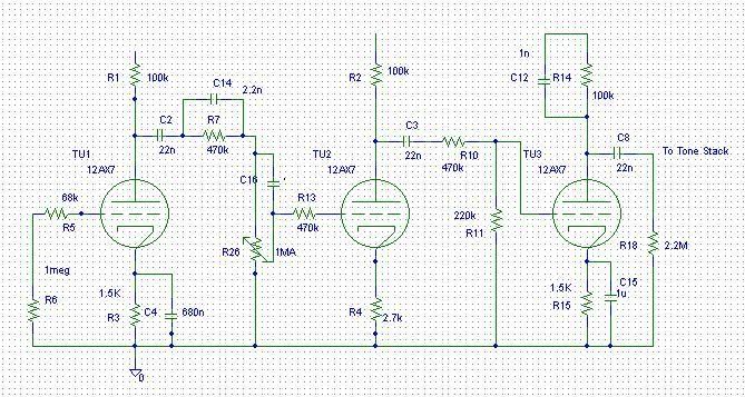
The loop section you may implantant between the tone stack and the master, what's IMO the best position in your application.
Larry
The fault almost always is sitting in front of the amp
Larry's Website now with included Pix's Gallery
Larry's Website now with included Pix's Gallery
-
EddyInChicago
- Senior Member
- Posts: 212
- Joined: Wed Jan 09, 2008 1:27 am
Larry's Tube Loop as a pedal
Hi All,
Dr. Larry,
If I was building your Tube Loop circuit as a pedal (eg: to be used as an external loop or jumping the send and return for boost), obviously I would need to design a power circuit/source for it. Here are my ideas and please give me yours and/or comment on mine.
1) I would use a "Flat Pack" Triad (FP230-50) transformer - going to -
2) a bridge rectifier - going to -
3) filter caps - going to POSIBLEY? -
4) choke - going to -
.....your tube loop circuit.
Now for the questions........
1) the flat pack puts out - 230.0V CT @ 0.05A - volts un-loaded, which I beleive will be around 325 volts after rectification and filtering. Would you suggest dropping the voltage by adding some value resistor before attachment to your loop circuit?
2) What voltage is good on the plates of the tube?
3) What value of capacitance would you use for filtering? How will different values affect the sound?
4) In a power supply circuit such as this, would you use a choke after the filter caps? If so, what value, rating...etc...?
Thank you for all your help.
Ed
-
novosibir
- Senior Member
- Posts: 4654
- Joined: Tue Nov 22, 2005 2:32 pm
- Just the numbers in order: 7
- Location: Nuernberg, Germany
- Contact:
1) rectifier - cap to ground - resistor - 2-nd cap to ground - loop voltage supply
2) Don't care about the voltage on the plate! Make a supply voltage of 300...330V
3) 16...22
2) Don't care about the voltage on the plate! Make a supply voltage of 300...330V
3) 16...22
The fault almost always is sitting in front of the amp
Larry's Website now with included Pix's Gallery
Larry's Website now with included Pix's Gallery