Metro JTM45 Build
Moderator: VelvetGeorge
-
BashCoder
-
bvmjethead
- Senior Member
- Posts: 195
- Joined: Mon Jan 24, 2005 4:34 pm
I'd be very grateful if one or more of you would take and post some close up pictures of the way you mounted your bias adjustment resistor on the JTM 45 board.
Being the resident idiot here I'd like photographic comparison to make sure I'm doing this right.
My board is populated with that one exception. Waiting on the shipment of plexi panels so I can continue from this point.
Having a blast so far! If anyone who is reading this is concerned with building this kit as their first.....let me tell you. If you can read these boards, read instructions with color photographs and just have a smidgen of common sense you can do this. It's great fun too.
Thanks in advance guy's.
-
BashCoder

-
bvmjethead
- Senior Member
- Posts: 195
- Joined: Mon Jan 24, 2005 4:34 pm
-
BashCoder
-
bvmjethead
- Senior Member
- Posts: 195
- Joined: Mon Jan 24, 2005 4:34 pm
I have the 15K resistor bridged between the two 10 UF caps.
It looks to me although I can't see it in the picture you posted that you must have that 15K resistor attatched to the variable bias control resistor, is this correct.
If so, can you widen up the picture you took so I can see the connection.
Also I guess the question is moot until I can test my circuits and determine if I even need to adjust my bias....
Do you HAVE TO have bias adjustment? I'm assuming I'll need it as I want to experiment with different valves to get the sound I like....
Thanks for all the help!
-
Jimy
- New Member
- Posts: 38
- Joined: Sat Dec 31, 2005 1:15 am
- Location: San-Ho-Zay, CA
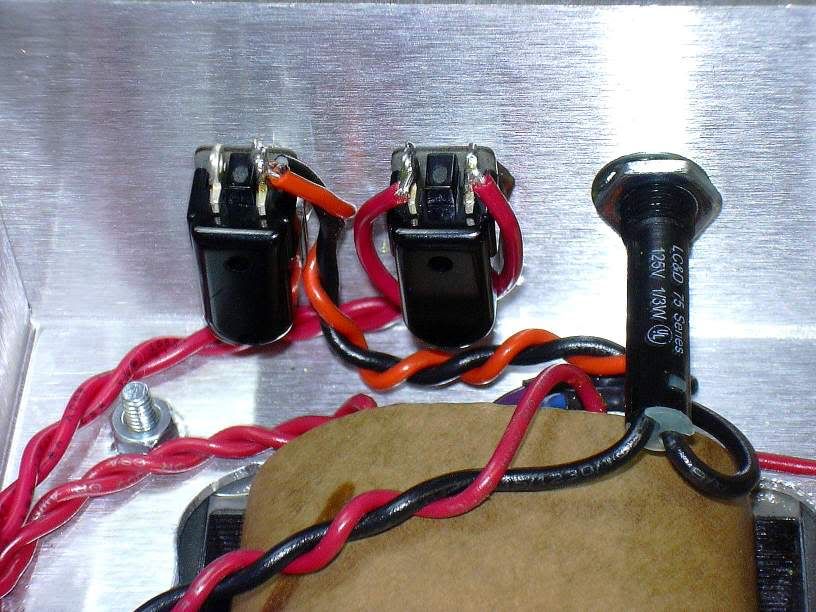
I came home tonight to find that my output transformer had arrived at last! So, after almost two weeks of downtime, I was FINALLY able to start building again. Good thing too. I was starting to go a little stir crazy.
I installed the tranny this evening and the chassis now has a nice satisfying heft to it. I had time to wire up the choke and OT primaries:
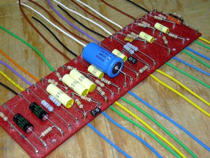
I also had time to rework the circuit board and install the 0.1uf Sozos. Thanks again to all the sharp eyed folks who caught my mistake. You really saved me some grief down the line.
I installed the tranny this evening and the chassis now has a nice satisfying heft to it. I had time to wire up the choke and OT primaries:
I also had time to rework the circuit board and install the 0.1uf Sozos. Thanks again to all the sharp eyed folks who caught my mistake. You really saved me some grief down the line.
-
BashCoder
-
bvmjethead
- Senior Member
- Posts: 195
- Joined: Mon Jan 24, 2005 4:34 pm
-
Jimy
- New Member
- Posts: 38
- Joined: Sat Dec 31, 2005 1:15 am
- Location: San-Ho-Zay, CA
-
Jimy
- New Member
- Posts: 38
- Joined: Sat Dec 31, 2005 1:15 am
- Location: San-Ho-Zay, CA
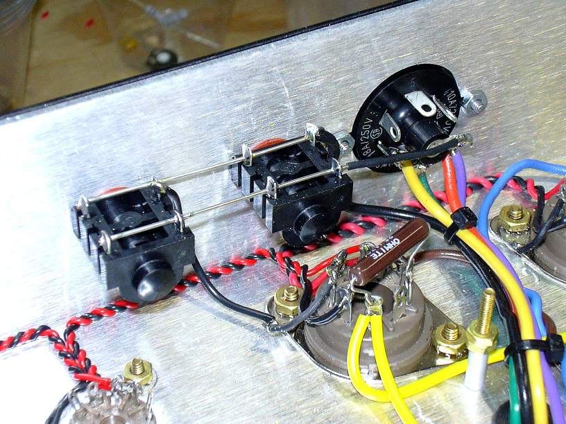
I managed to squeeze in a little bench time yesterday. I installed the front panel and connected the switches and lamp:
At this point, the power section is nearly done. One little gotcha I should mention is that I found it very hard to connect the red wire that goes from the standby switch to the rear lug of the big filter cap. The hole on the cap's lug was already filled with two wires and solder, making it very hard to get the new wire properly installed. If I ever do this again, I'll leave this connection unsoldered until all three wires are in place.

At this point, the power section is nearly done. One little gotcha I should mention is that I found it very hard to connect the red wire that goes from the standby switch to the rear lug of the big filter cap. The hole on the cap's lug was already filled with two wires and solder, making it very hard to get the new wire properly installed. If I ever do this again, I'll leave this connection unsoldered until all three wires are in place.
-
Jimy
- New Member
- Posts: 38
- Joined: Sat Dec 31, 2005 1:15 am
- Location: San-Ho-Zay, CA
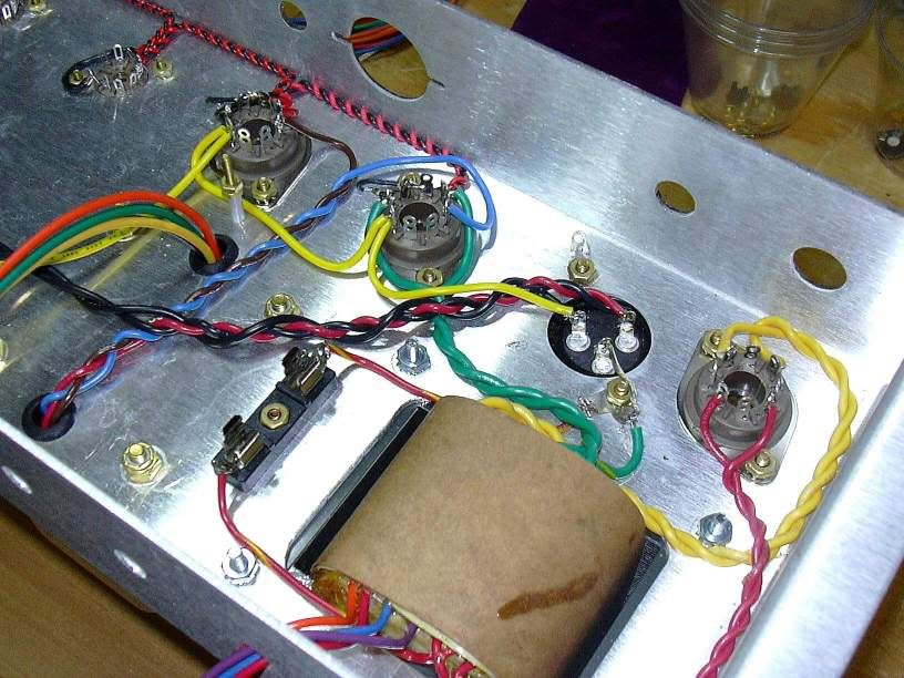
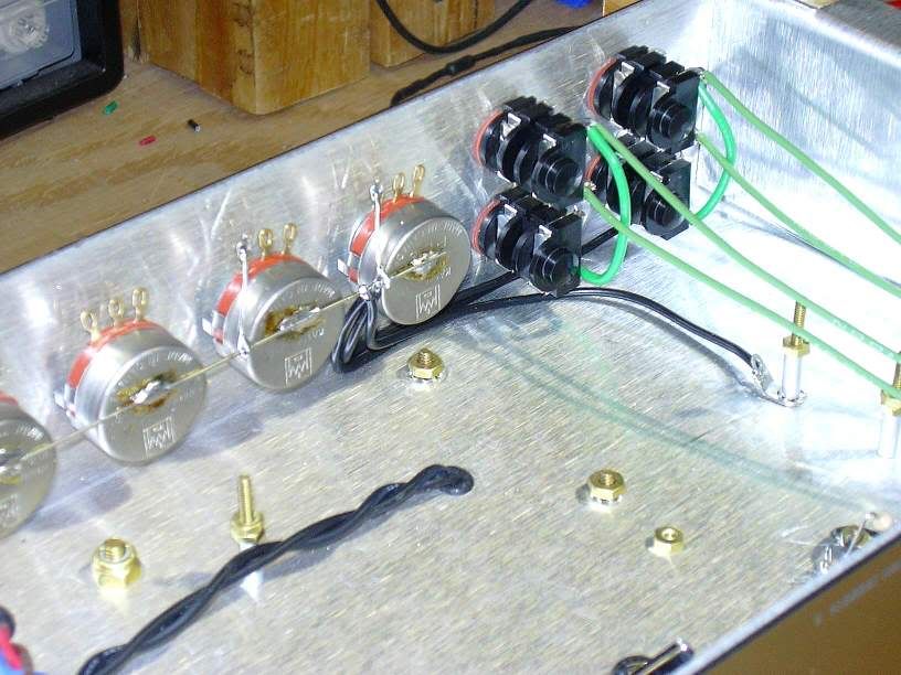
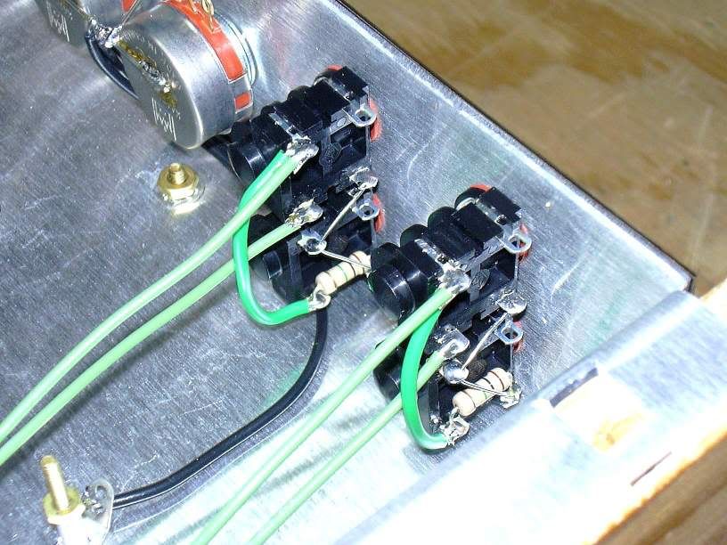
Well it's starting to look like an amp. On Sunday I installed the input jacks and all the pots. Turns out soldering to the backs of the PEC pots was more trouble than I expected. I know that Alpha pots are a bear, but I'd hoped that the PEC's would be easier. Nope. You need to sand or file 'em to make the solder really stick.
With regards to the input jacks, a little trick someone showed me a while back: Make all your connections on the lower jack before you install it. You should have the 1M resistor, the ground wire, the green jumper wire, and the bare jumper wire all soldered in place before you install the lower jack in the chassis. Then all you have to do is install the upper jack, and make the remaining couple of connections in place.
Last night I dropped in the circuit board and next up is wiring the tube sockets. Unfortunately, my camera's batteries died right after I finished the jacks, so no pictures of the board until I buy more batteries... hopefully tonight.
-
Flames1950

- Senior Member
- Posts: 9294
- Joined: Sun Feb 08, 2004 1:04 am
- Location: Waukee, Iowa
