Here is an update of the layout.
missing the light indicator correct connections, and the pots ground, and maybe other things.
Edit : picture erased for the update
JTM 45/100 - Build story
Moderator: VelvetGeorge
-
Xplorer

- Senior Member
- Posts: 2480
- Joined: Sun Apr 19, 2009 5:27 pm
- Just the numbers in order: 7
Re: JTM 45/100 - Build story
Last edited by Xplorer on Mon Sep 17, 2012 5:26 pm, edited 1 time in total.
-
neikeel

- Senior Member
- Posts: 7231
- Joined: Tue Dec 06, 2005 8:31 am
- Location: Suffolk, England
Re: JTM 45/100 - Build story
One of the jack ground wires on that amp is brown..........
If you want a grounding system that works well but does not involve the extra wires that Larry grounding has I use the system SDM uses.
This keeps the lug by the inputs for the preamp cathodes and inputs. The bus wire on the back of the pots is cut short - the bass and presence pots are not attached.
The presence pot then has its own dedicated black wire which goes to the ground of the PI capacitor.
Neil
-
AJW
- Senior Member
- Posts: 324
- Joined: Mon Jul 30, 2007 5:16 pm
- Just the numbers in order: 13492
Re: JTM 45/100 - Build story
The brown wire to the output jacks goes to ground, not the output of the impedance selector. This will be a really useful diagram once it is sorted out! I wish I had something like that when I was building mine.
-
Xplorer
- Senior Member
- Posts: 2480
- Joined: Sun Apr 19, 2009 5:27 pm
- Just the numbers in order: 7
Re: JTM 45/100 - Build story
What is SDM please ?
So you're describing a third option for the grounding ?
Is the one of this latout still ok ? ( the brown wire or both pairs of jacks directly linked i guess )
Although what's left would be : where is this buss wire of the pots connected on the chassis ?
Is your grounding system the same as mine, except for what you described for the pots ?
I'm not sure to follow and i'd need to see this at home.
Thanks, i'll look at these brown wires at home and update the layout from what i understand. ^^
-
Xplorer
- Senior Member
- Posts: 2480
- Joined: Sun Apr 19, 2009 5:27 pm
- Just the numbers in order: 7
Re: JTM 45/100 - Build story
Oh yes ! I see my mistake !
I designes the output jacks ground on the tip side, where the output of the impedance selectors goes. I'll correct it thanks !
I designes the output jacks ground on the tip side, where the output of the impedance selectors goes. I'll correct it thanks !
-
neikeel
- Senior Member
- Posts: 7231
- Joined: Tue Dec 06, 2005 8:31 am
- Location: Suffolk, England
Re: JTM 45/100 - Build story
Careful with your thread!
You are jumping back and forth between output jack grounds/wiring and input jacks and wiring - you may get the answer in a post to the wrong question!
You are jumping back and forth between output jack grounds/wiring and input jacks and wiring - you may get the answer in a post to the wrong question!
Neil
-
Xplorer
- Senior Member
- Posts: 2480
- Joined: Sun Apr 19, 2009 5:27 pm
- Just the numbers in order: 7
Re: JTM 45/100 - Build story
I didn't realise. Yes, i may mix things and design a dangerous stuff.
To make it correct, what should i do about
The input jacks
The output jacks
The light indicator
Where should i ground the buss wire of the back of the pots ?
Anything else ?
To make it correct, what should i do about
The input jacks
The output jacks
The light indicator
Where should i ground the buss wire of the back of the pots ?
Anything else ?
-
neikeel
- Senior Member
- Posts: 7231
- Joined: Tue Dec 06, 2005 8:31 am
- Location: Suffolk, England
Re: JTM 45/100 - Build story
You ground the pot bus wire to the same point as the input jacks and preamp cathodes and preamp filter can.Xplorer wrote: To make it correct, what should i do about:
The input jacks
Where should i ground the buss wire of the back of the pots ?
Output jacks are grounded via the lugs closest to the chassis (as is the common wire from the OT secondaries). I find the OT wire quite thick but like to feed it and the bus wire through the lug hole for a good physical joint before soldering and then do the same on the other output jack to ground.Xplorer wrote: The output jacks
The light indicatorAnything else ?
The lamp can be 6.3v hooked up directly to the heater lugs on the PT - by far easiest and simplest - the way the originals were done (more difficult when the Dagnall PTs are wires only, no lugs!)
Neil
-
Xplorer
- Senior Member
- Posts: 2480
- Joined: Sun Apr 19, 2009 5:27 pm
- Just the numbers in order: 7
Re: JTM 45/100 - Build story
i really didn't see a wire coming from the pots or buss wire on the pots, going to this ground point. mystery !
my lamp is rated for 240v and i tested it at 120v : it had light but not a strong light. So i'll have to send about 220v - 230v : what wil be used actualy in the primary. I'm just not sure where to connect it : i thought about connecting it in serie after the pin coming from the ac, going to the primary. ( any good ? or a better idea ? )
my lamp is rated for 240v and i tested it at 120v : it had light but not a strong light. So i'll have to send about 220v - 230v : what wil be used actualy in the primary. I'm just not sure where to connect it : i thought about connecting it in serie after the pin coming from the ac, going to the primary. ( any good ? or a better idea ? )
isn't the common connected to the fuse ?Output jacks are grounded via the lugs closest to the chassis (as is the common wire from the OT secondaries).
- Attachments
-
- pots buss wire.jpg
- (416.77 KiB) Downloaded 616 times
-
neikeel
- Senior Member
- Posts: 7231
- Joined: Tue Dec 06, 2005 8:31 am
- Location: Suffolk, England
Re: JTM 45/100 - Build story
The fuse is connected to the centre tap of the power/mains transformer secondary 
My 45/100 has a wire from the bus bar to the PI cap ground:
http://i76.photobucket.com/albums/j2/ne ... c09008.jpg
But Steve's layout has it grounded at the other end.................
The lamp can be hooked directly to the 240v lugs on your PT - direct.
My 45/100 has a wire from the bus bar to the PI cap ground:
http://i76.photobucket.com/albums/j2/ne ... c09008.jpg
But Steve's layout has it grounded at the other end.................
The lamp can be hooked directly to the 240v lugs on your PT - direct.
Neil
-
Xplorer
- Senior Member
- Posts: 2480
- Joined: Sun Apr 19, 2009 5:27 pm
- Just the numbers in order: 7
Re: JTM 45/100 - Build story
The fuse is connected to the centre tap of the power/mains transformer secondary
i meant, the other fuse. my brain is starting to get mixed ha ha
the common goes to the pannel mounted fuse, then from there, to the "N" of the bulgin plug. is it wrong ? i'm surprised that you said it had to be grounded, and to the same lug as the output jacks ground ( ? )
thanks for your picture ! so it's what i see on the picture ?
i updated the layout this way. But on the George's amp i still don't see it, any side
are you saying that if i'm using the 230v tap for the primary , i can still use the 240v wire left , for the light indicator ? here i'm really confused, when it seems simple in the end.The lamp can be hooked directly to the 240v lugs on your PT - direct.
one side of the light indicator should be connected where ?
and the other side, where too ?
grounding the pots with the buss wire connected to the ground of the power caps board is ok you think ? well, since your amp is set this way i guess it's ok !
- Attachments
-
- pots grounding.jpg
- (212.86 KiB) Downloaded 612 times
Last edited by Xplorer on Tue Sep 18, 2012 3:07 pm, edited 1 time in total.
-
Xplorer
- Senior Member
- Posts: 2480
- Joined: Sun Apr 19, 2009 5:27 pm
- Just the numbers in order: 7
Re: JTM 45/100 - Build story
An update of the layout.
i'll connect the light indicator with one side on the AC switch ( on the side of the PT ) , and one side after the pannel fuse, so on "F" common.
i'm unsure of where to ground the power caps board, i couldn't see it on pictures of originals.
Please, if anybody see something wrong or not accurate, or something that could be improved, let me know !
- Attachments
-
- Connections layout 12.pdf
- (1.14 MiB) Downloaded 351 times
-
Xplorer
- Senior Member
- Posts: 2480
- Joined: Sun Apr 19, 2009 5:27 pm
- Just the numbers in order: 7
Re: JTM 45/100 - Build story
Some pictures of the progress.
-
shakti
- Senior Member
- Posts: 2053
- Joined: Tue Apr 05, 2005 9:06 am
- Just the numbers in order: 7
- Location: Ramnes, Norway
Re: JTM 45/100 - Build story
RS style indicator? Very cool. The ones you can get on Ebay are all but identical to the RS labeled ones. They are red and not amber/orange, which isn't 100% accurate for a '66ish JTM45 or JTM45/100, but the red ones were used for many of the earlier block logo amps. I used one for my JTM45/100 as well, an orange one would have been perfect, but I still prefer it to the modern lamps.
JTM45 RS OT, 1973 18W, JTM45/100, JTM50, JMP50 1986, JMP100 "West Coast", AC15, AC30, BF Super Reverb, Boogie Mk 1, Hiwatt CP103, DR103
-
Xplorer
- Senior Member
- Posts: 2480
- Joined: Sun Apr 19, 2009 5:27 pm
- Just the numbers in order: 7
Re: JTM 45/100 - Build story
yes, i like it too, although it's red, but not a problem to me, that's ok. and it handles the power i need.
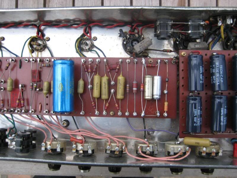
i noticed something on George's amp : on the output jacks there's
'one wire going to the ground,
-one wire going to the output of the impedance selector,
-one wire from the OT i guess,
and an extra wire ( compared to the layout i uploaded ) , a black wire. i really have no idea of what this is.
plus, under the jacks, there's this blue wire ... and a pink wire at the same point.
normaly it should be a black wire from the OT at this point. so ... mystery ...
- Attachments
-
- output jacks.jpg
- (571.29 KiB) Downloaded 568 times