hey guys
my Les Paul wiring kit came the other day, but my pickups havnt yet,
ive wired some strats before, but never a les paul, so i havnt used sheilded wire before, and i was wondering how i use it?
do i just pull back the outside, and use the inside like i would a normal piece of wire??
Sheilded Wire
Moderators: VelvetGeorge, BUG
-
TomGibbs

- Senior Member
- Posts: 335
- Joined: Sun Apr 16, 2006 2:06 pm
- Just the numbers in order: 7
- Location: Wales, UK
- Contact:
-
908ssp

- Senior Member
- Posts: 2954
- Joined: Sun Aug 14, 2005 12:56 pm
- Just the numbers in order: 7
- Location: Michigan
- Contact:
I figure a picture is worth a thousand words. This is a real 59.
- Attachments
-
- RealDeal59-c.jpg
- (75.36 KiB) Downloaded 471 times
-
TomGibbs
- Senior Member
- Posts: 335
- Joined: Sun Apr 16, 2006 2:06 pm
- Just the numbers in order: 7
- Location: Wales, UK
- Contact:
thanks alex, but im only confused on one thing now,
i get how it links up in the cavity, but what about the switch?
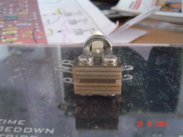
ive got the switchcraft toggle switch in front of me, and it seems my switch isnt the sdame as the one in the diagram
on one end, its got two prons, and three on the other with the middle one being the biggest, can someone tell me how i wire it please??
i THINK this is how to do it ;
solder the left lug from the side which has two, using the inside of the shielded wire, and solder the outside to the left lug at the opposite end, would that work?
or do i need to use the inside of the wire for both lugs?
i get how it links up in the cavity, but what about the switch?
ive got the switchcraft toggle switch in front of me, and it seems my switch isnt the sdame as the one in the diagram
on one end, its got two prons, and three on the other with the middle one being the biggest, can someone tell me how i wire it please??
i THINK this is how to do it ;
solder the left lug from the side which has two, using the inside of the shielded wire, and solder the outside to the left lug at the opposite end, would that work?
or do i need to use the inside of the wire for both lugs?

-
bluze81
- Senior Member
- Posts: 1403
- Joined: Tue Jun 27, 2006 8:36 am
- Just the numbers in order: 7
- Location: paradise mid america, los angeles CA native
Tom, the switch has the 3 lugs ,the middle big one is ground,the outer part of the sheilded wire is also ground,the outer lugs of the switch will be for each pick up, post a picture so we can make shure of the type of switch you have,as there are different configurations.. also just study the switch as you move the selector button you can see how it works, you should have 2 leads of the wire coming from the control cavity to switch [1 for each pickup.] the inner part of the wire will be the positive. hope this helps you.
-
TomGibbs
- Senior Member
- Posts: 335
- Joined: Sun Apr 16, 2006 2:06 pm
- Just the numbers in order: 7
- Location: Wales, UK
- Contact:
-
Guitar Adjuster

- Senior Member
- Posts: 1560
- Joined: Mon Oct 31, 2005 8:34 pm
- Location: San Antonio
-
TomGibbs
- Senior Member
- Posts: 335
- Joined: Sun Apr 16, 2006 2:06 pm
- Just the numbers in order: 7
- Location: Wales, UK
- Contact:
thanks guitar adjuster, but that diagram came with teh pickups i ordered, and i have been using it through most of the wiring,
i THINK ive found the answer through googling:
The ground goes to the heavy lug - it grounds the switch body.
The 2 outside lugs are connected to either hot wire from the pick-ups (or the lead wire leading to the switch from the control cavity).
The 2 inside tabs are wired together and are the output of the switch leading back to the control cavity where they're hooked up to your output-jack.
thanks again everyone and ill go give it a try now
-
bluze81
- Senior Member
- Posts: 1403
- Joined: Tue Jun 27, 2006 8:36 am
- Just the numbers in order: 7
- Location: paradise mid america, los angeles CA native
TomGibbs wrote:thanks guitar adjuster, but that diagram came with teh pickups i ordered, and i have been using it through most of the wiring,
i THINK ive found the answer through googling:
The ground goes to the heavy lug - it grounds the switch body.
The 2 outside lugs are connected to either hot wire from the pick-ups (or the lead wire leading to the switch from the control cavity).
The 2 inside tabs are wired together and are the output of the switch leading back to the control cavity where they're hooked up to your output-jack.Tom thats exactly how I hook up this type of switch, will work fine, bend the two tabs out away from the ground tab, and it gives you a bit more room to work with the leads. and dont forget to solder the two tabs on the oposite side ,I run a small wire thru them, good work!
thanks again everyone and ill go give it a try now