I'm not very knowledgeable about rectifier circuits, so if this question is answered better by a reference to some online tutorial, feel free to guide me in that direction.
I was wondering if there's a technical difference between a bridge rectifier, like the one used in Metroamp's 50W kits, and a setup using diodes. Many early ('67-'68) 50W amps simply had diodes soldered directly to the power transformer HT leads. Probably not a very safe way of doing it, but I was wondering if there are any technical advantages or disadvantages with one method of (solid state) rectification over the other, and how that could translate to a difference in sound or feel. Would it be better to use diode rectification with FREDs, or is the bridge rectifier superior...? This is what I'm getting at...
Bridge rectifier vs diodes?
Moderator: VelvetGeorge
-
shakti
- Senior Member
- Posts: 2053
- Joined: Tue Apr 05, 2005 9:06 am
- Just the numbers in order: 7
- Location: Ramnes, Norway
Bridge rectifier vs diodes?
JTM45 RS OT, 1973 18W, JTM45/100, JTM50, JMP50 1986, JMP100 "West Coast", AC15, AC30, BF Super Reverb, Boogie Mk 1, Hiwatt CP103, DR103
-
jcmjmp
- Senior Member
- Posts: 724
- Joined: Tue Apr 01, 2008 9:48 am
- Just the numbers in order: 7
- Location: Quebec, Canada
Re: Bridge rectifier vs diodes?
A bridge rectifier is a single package version of a 4 individual diode rectifier and is usually setup for a single tap (no center tap) voltage source from the PT (vs center tapped output).
http://hyperphysics.phy-astr.gsu.edu/Hb ... ectbr2.gif" onclick="window.open(this.href);return false;
A standard bridge rectifier cannot be used with a center tapped PT i.e.
http://hyperphysics.phy-astr.gsu.edu/Hb ... ectct2.gif" onclick="window.open(this.href);return false;
Well, you could use it but it would be a waste of space and money because you'd be using half of it. I've never done it but I guess it could be done.
Electronically, there is no difference. With individual diodes, you have more flexibility and as you say, you can experiment with fred or fast recovery diodes.
-
neikeel

- Senior Member
- Posts: 7231
- Joined: Tue Dec 06, 2005 8:31 am
- Location: Suffolk, England
Re: Bridge rectifier vs diodes?
My understanding is that the 100w amps use a bridge type rectifier with the voltage doubler type circuit.
Here you need the 4 diodes. The PT does have a centre tap but that is run to a point between the first two filter caps to even out the voltages across caps which are of variable (+/- 10% values).
Exception is the JTM45/100 which has 3 diodes pretty much as the 50watter arrangement:
In a 50 watt most amps use the 1A rated diodes but in series pairs for each half of the PT, the centre tap on this is to chassis earth.
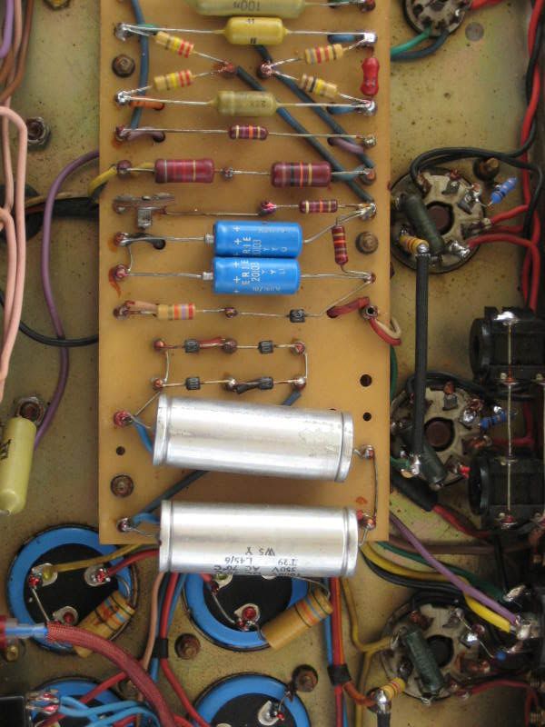
On the amps with the diode block you are only actually using two of the diodes (the fourth terminal that is earthed on a 100watter is left unused see below).
http://amparchives.com/album/Marshall/5 ... 85a_3.html
I personally would use the 3A rated diodes in pairs on a new build 50watter for a safety margin.
There are probably more erudite opinions around and I sit back for them to pour forth
Here you need the 4 diodes. The PT does have a centre tap but that is run to a point between the first two filter caps to even out the voltages across caps which are of variable (+/- 10% values).
Exception is the JTM45/100 which has 3 diodes pretty much as the 50watter arrangement:
In a 50 watt most amps use the 1A rated diodes but in series pairs for each half of the PT, the centre tap on this is to chassis earth.
On the amps with the diode block you are only actually using two of the diodes (the fourth terminal that is earthed on a 100watter is left unused see below).
http://amparchives.com/album/Marshall/5 ... 85a_3.html
I personally would use the 3A rated diodes in pairs on a new build 50watter for a safety margin.
There are probably more erudite opinions around and I sit back for them to pour forth
Neil
-
flemingmras

- Senior Member
- Posts: 2532
- Joined: Fri Mar 19, 2004 1:39 am
- Just the numbers in order: 7
- Location: Rohnert Park, CA
- Contact:
Re: Bridge rectifier vs diodes?
IMHO, in the case of solid state rectifiers you're not gonna hear a tonal difference between different rectifier circuits. It's not even an area of the amp worth screwing with. Rectifiers either work or they don't, plain and simple.
In regards to the "voltage doubler" circuit...that as has been said before is a matter of semantics. If you look at it as if you're doubling the center tap voltage, then yeah you could say it's a voltage doubler. But hooking up across the full winding without the center tap connected will give you the same end result, but you'll have to install bleeder resistors across the first stage filter caps to keep the voltage on the caps balanced. This circuit is more of a full wave voltage balancer as it is used to allow each half of the HT secondary to charge the first filter caps instead of using bleeder resistors to do it. Since each half of the HT secondary is 1/2 the voltage of the full HT secondary, you get 1/2 the voltage on each cap and each cap on the first filtering stage sees the same voltage to prevent one from going overvoltage.
Now a note on voltage doubler circuits...all they are is a dual polarity rectifier with the negative supply output grounded instead of the 1/2 voltage point being the ground reference. This gives you the "peak to peak" value of the incoming AC (i.e. the voltage measured from the negative peak to the positive peak), which is double the "peak" value (the voltage measured from 0 volts to the positive peak on one side of the supply and the voltage measured from 0 volts to the negative peak on the other side), rather than just the "peak" value of both halves of the AC signal. This is how it "doubles" the voltage output. Since the filter caps are in series, just like with batteries you get double the voltage out since the positive peak charges 1 cap while the negative peak charges the other. Due to the way the cap is oriented in a positive fashion relative to ground, you get a positive voltage out of the cap that's charged by the negative peak.
Look in the MetroAmp Wiki in the Tube Amp Power Supplies section...I've written articles there covering the operation of each type of rectifier that you'll find in a tube amp. The link to the Rectifier Circuits section is posted below.
Rectifier Circuits
As was stated above, a bridge rectifier is a self contained unit with 4 diodes hooked up in a bridge configuration and will perform the same as hooking up 4 individual diodes in a bridge config, just like the 100 watt Marshalls.
There's just that fine line between stupid and clever - Nigel Tufnel
-
shakti
- Senior Member
- Posts: 2053
- Joined: Tue Apr 05, 2005 9:06 am
- Just the numbers in order: 7
- Location: Ramnes, Norway
Re: Bridge rectifier vs diodes?
Thanks guys! The answer is usually closer to home than you think...I should spend more time on the Wiki!
Just one thing; some of you say the rectifier isn't worth poring over, yet some people say that using FREDs will have an effect particularly on the high end. I'm ready to believe that changes in the power amp section will affect the overall sound and feel (witness the difference between different filter cap brands, let alone ratings), but as far as the rectifier, I've never done any experimentation. I did have a tech install FREDs in a '71 1986 years ago. The amp came back sounding fantastic, but I changed tubes in the same operation, so that's not much to base any opinion on...
Just one thing; some of you say the rectifier isn't worth poring over, yet some people say that using FREDs will have an effect particularly on the high end. I'm ready to believe that changes in the power amp section will affect the overall sound and feel (witness the difference between different filter cap brands, let alone ratings), but as far as the rectifier, I've never done any experimentation. I did have a tech install FREDs in a '71 1986 years ago. The amp came back sounding fantastic, but I changed tubes in the same operation, so that's not much to base any opinion on...
JTM45 RS OT, 1973 18W, JTM45/100, JTM50, JMP50 1986, JMP100 "West Coast", AC15, AC30, BF Super Reverb, Boogie Mk 1, Hiwatt CP103, DR103
-
flemingmras
- Senior Member
- Posts: 2532
- Joined: Fri Mar 19, 2004 1:39 am
- Just the numbers in order: 7
- Location: Rohnert Park, CA
- Contact:
Re: Bridge rectifier vs diodes?
And the same people who claim the FRED diodes make any difference are probably the same guys who claim that Monster brand speaker cable is the best sounding speaker cable on the market...the same people who came from the audiophile/hi-fi community (i.e. "audiophools") at one time too. And some people claim to hear things they THINK they hear that they really don't...because when people listen for subtle things, they hear what they wanna hear...especially if they spent a lot of money on what it was they had changed on something. Helps them justify spending the large amount of money they just spent.shakti wrote:Thanks guys! The answer is usually closer to home than you think...I should spend more time on the Wiki!
Just one thing; some of you say the rectifier isn't worth poring over, yet some people say that using FREDs will have an effect particularly on the high end. I'm ready to believe that changes in the power amp section will affect the overall sound and feel (witness the difference between different filter cap brands, let alone ratings), but as far as the rectifier, I've never done any experimentation. I did have a tech install FREDs in a '71 1986 years ago. The amp came back sounding fantastic, but I changed tubes in the same operation, so that's not much to base any opinion on...
I never did understand why people try hi-fi tricks on guitar amps that were never meant to be a hi-fi amp, and wouldn't sound nearly as good if they were. The fact that they're far from hi-fi is what makes them what they are. Leave them imperfect like they are...that's why they sound as good as they do.
Filtering will affect the dynamic feel and tone of the amp..to a point. It depends on how much filtering the amp started out with. If it was a low filtered power supply to begin with, then increasing the filtering will have a dramatic effect. However, if the amp already has decent filtering and you step it up beyond that, you won't have as drastic of an effect. Eventually you reach the point of diminishing returns, and no amount of filtering increase will make a difference.
The filter circuit is the "current reservoir" of the amp...when you run the amp hard that has a low filtered power supply, there's not as much current in reserve for the tubes to pull, so the filter caps discharge quicker, causing the power supply voltage to drop. Some refer to this as "sag". But when you do it on an amp that has high filtering, there's more current stored by the filter caps, so the power supply voltage doesn't drop near as much. This affects the tightness of the amp. But again, once you reach the point where the filter circuit has sufficient filtering, you won't hardly notice a difference.
Here's another article in the Wiki regarding filter circuits, their components and what they do.
Filter Circuit Components
There's just that fine line between stupid and clever - Nigel Tufnel
-
paulster
- Senior Member
- Posts: 620
- Joined: Mon Mar 13, 2006 4:25 pm
- Just the numbers in order: 7
- Location: Los Angeles & London
Re: Bridge rectifier vs diodes?
There have actually been some comparisons and clips done here which, if you accept the comparison method, clearly show a difference between regular 1N4007s and fast recovery diodes.flemingmras wrote:IMHO, in the case of solid state rectifiers you're not gonna hear a tonal difference between different rectifier circuits. It's not even an area of the amp worth screwing with. Rectifiers either work or they don't, plain and simple.
These threads give a lot of useful information on what you might expect:
http://forum.metroamp.com/viewtopic.php?f=4&t=12141" onclick="window.open(this.href);return false;
http://forum.metroamp.com/viewtopic.php?f=4&t=14392" onclick="window.open(this.href);return false;
http://forum.metroamp.com/viewtopic.php?f=4&t=14053" onclick="window.open(this.href);return false;
http://forum.metroamp.com/viewtopic.php?f=3&t=8724" onclick="window.open(this.href);return false;
I'll stick with my ultra-fast diodes, thanks.
-
jcmjmp
- Senior Member
- Posts: 724
- Joined: Tue Apr 01, 2008 9:48 am
- Just the numbers in order: 7
- Location: Quebec, Canada
Re: Bridge rectifier vs diodes?
Regardless of the tonal benefits of having fast recovery diodes or FREDs, I believe that there are benefits in terms or spikes and switching noise going into the circuit and back into the PT.
Some say that snubber caps can have the same effect as a fast recovery diode.
Some say that snubber caps can have the same effect as a fast recovery diode.
-
Roe
- Senior Member
- Posts: 5056
- Joined: Thu Apr 13, 2006 1:36 pm
- Just the numbers in order: 7
- Location: Drontheim. Norwegen
- Contact:
Re: Bridge rectifier vs diodes?
does the bridge rectifer george supplies in the 50w kit feature ultra fast diodes?
http://www.myspace.com/20bonesband" onclick="window.open(this.href);return false;
http://www.myspace.com/prostitutes" onclick="window.open(this.href);return false;
Super 100 amps: 1202-119 & 1202-84
JTM45 RS OT JTM50 JMP50 1959/2203/34/39
http://www.myspace.com/prostitutes" onclick="window.open(this.href);return false;
Super 100 amps: 1202-119 & 1202-84
JTM45 RS OT JTM50 JMP50 1959/2203/34/39
-
paulster
- Senior Member
- Posts: 620
- Joined: Mon Mar 13, 2006 4:25 pm
- Just the numbers in order: 7
- Location: Los Angeles & London
Re: Bridge rectifier vs diodes?
Most bridge rectifier modules use generic 1N400x type specification diodes, but there are exceptions. You need to know the part number of the item in question and look up its specifications and/or data sheet to find out exactly what you're going to get.
I can't help you on the specifics of George's one, unfortunately.
I can't help you on the specifics of George's one, unfortunately.
-
flemingmras
- Senior Member
- Posts: 2532
- Joined: Fri Mar 19, 2004 1:39 am
- Just the numbers in order: 7
- Location: Rohnert Park, CA
- Contact:
Re: Bridge rectifier vs diodes?
Most self-contained rectifiers are 4 regular standard diodes on a common substrate.paulster wrote:Most bridge rectifier modules use generic 1N400x type specification diodes, but there are exceptions. You need to know the part number of the item in question and look up its specifications and/or data sheet to find out exactly what you're going to get.
I can't help you on the specifics of George's one, unfortunately.
There's just that fine line between stupid and clever - Nigel Tufnel
-
neikeel
- Senior Member
- Posts: 7231
- Joined: Tue Dec 06, 2005 8:31 am
- Location: Suffolk, England
Re: Bridge rectifier vs diodes?
George's is pretty much the same, I asked him about their spec a while ago as I was concerned about the (or was it Flames  ). He did say the spec was superior to the originals you see in the early 70s.
Neil