My new build ,high volyage readings
-
fixer2
- Senior Member
- Posts: 212
- Joined: Wed Jul 29, 2015 7:23 pm
- Just the numbers in order: 13492
Re: My new build ,high volyage readings
I can not seem to get my pictures uploaded I get the message sorry , the board attachment quota has been reached.does this mean I have to start another post .I do have a few pictures on the first page of this topic ,but I can not seem to get the puicture of the in puts posted
-
danman
- Senior Member
- Posts: 1099
- Joined: Tue Sep 10, 2013 9:09 pm
- Just the numbers in order: 13492
Re: My new build ,high volyage readings
To post images you must upload your pics to an image hosting site and then include the url in your OP. I'm not very computer literate so I still have not learned how to do this myself.
-
fixer2
- Senior Member
- Posts: 212
- Joined: Wed Jul 29, 2015 7:23 pm
- Just the numbers in order: 13492
Re: My new build ,high volyage readings
I just click upload on here and it worked back when I first put my pictures on ,page one now it stoped working I have nt change any thing .I am not a computer guy .
-
danman
- Senior Member
- Posts: 1099
- Joined: Tue Sep 10, 2013 9:09 pm
- Just the numbers in order: 13492
Re: My new build ,high volyage readings
I wish that I could help but I am not very computer savvy myself...lol! I just went back to the 1st page and clicked on a couple of your original pics. I didn't notice before but it is very possible that you may have cooked some of your components during the soldering process. There is way to much solder on quite a few turrets and in some places it looks like solder is bridging across more than one turret. With as much solder as you have applied, it is very likely that you had the heat on delicate components way to long. The iron should be on and off of the joint in less than five seconds to avoid damaging items such as silver mica capacitors. It is also advisable to use a heat sink to help draw away some of the excess heat. Just be sure to go through the amp carefully and make sure that solder has not bridged itself across any two items that are not suppose to be connected. You may also want to check your small caps for any signs of damage.
-
fixer2
- Senior Member
- Posts: 212
- Joined: Wed Jul 29, 2015 7:23 pm
- Just the numbers in order: 13492
Re: My new build ,high volyage readings
How would I tell if the small cap are good or bad ,do they leak .Or can I put a tester on them and see if I get a ohm read threw them .I guess I got solder happy because I should have used some kind of cleaner on the turrets .I want to get this one figure out ,so then I can build another one but this time much more cleaner neater etc. . I would like to do some mods to it so sounds differnt than this one so I can use them both by switching from one or the other.Thats my plans.I will go know and look again at the turrets really close it has there.Thanks
-
danman
- Senior Member
- Posts: 1099
- Joined: Tue Sep 10, 2013 9:09 pm
- Just the numbers in order: 13492
Re: My new build ,high volyage readings
The small caps would likely need to be removed from the circuit to get an accurate capacitance reading with a multimeter. The time spent unsoldering them may also cause damage to if you are not quick with the iron. Capacitors really need to be checked at full operating voltages but this requires special equipment that you may not have. Certain resistors could be checked while in circuit but others will give you false readings unless they are removed from the circuit for testing. At this point I would not worry so much about removing and checking them though. Definitely make sure that you do not have any solder bridges across any tube socket pins and turrets or any solder blobs that may be hanging below the board and shorting out. Do you have any techs in your area or any friends that are skilled in troubleshooting tube amps? With the right equipment it would not take long to find out where you are losing the signal but trying to explain the process over the internet can be very difficult.
-
fixer2
- Senior Member
- Posts: 212
- Joined: Wed Jul 29, 2015 7:23 pm
- Just the numbers in order: 13492
Re: My new build ,high volyage readings
I just got a desoldering Iron /sucker so Iam going to remove the caps just after where I stop getting voltage readings which is in the middle of the 3rd and 4th jumper wire connection so this may be cold or burnt or dirty in deep ,and how fully this is why v2 and v3 are not getting there voltage that we have gone threw so they are not power up to work just the heaters on the that is all.I just may replace those caps and put new ones in using a heat sink too.Just wish I could put a picture on to get some more input from you guys first.I made a audio tester sending a guitar signal in to one of the inputs turn the amp on in play mode and probe around from the input jacks and threw the board and got good sound on the input jacks much less on the other ins of tube 1 V1 but alot louder on the V2 and then it did not go any further ,can some one draw out from input to v1 then the vol control or tone controls and to V2,thenV3 then the power tubes ,basially how the signal is the correct way to go on a Marshall jtm 45 .I have google on few differnt ways each time and get no info on Marshalls some fender amps but they are not just like mine,so here I have to be picky because something is not right in this build I started out not getting a correct voltage reading on V3,then after some testing found out I get no sound at all when I plug my guitar in .
-
neikeel

- Senior Member
- Posts: 7231
- Joined: Tue Dec 06, 2005 8:31 am
- Location: Suffolk, England
Re: My new build ,high volyage readings
Suggest you open a photobucket account. The Metro board has some limited capacity for pictures but when you exceed your limit you need to remove some pics to allow new ones in. If you use a host like photobucket (any will do, it is jus that I use photobucket and it works well for what I do) you can post an IMG address like this:

To post a link to a site or image page you use inserted address
On photobucket you just double click the direct link on the site and use the img button that you see above the typing box (like I am using now) and then paste the direct link in between the codes
codes
That will help a lot if we can see where you are.
eg pics of my first JTM45 build a while back: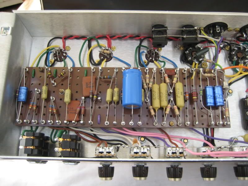
To post a link to a site or image page you use inserted address
On photobucket you just double click the direct link on the site and use the img button that you see above the typing box (like I am using now) and then paste the direct link in between the
That will help a lot if we can see where you are.
eg pics of my first JTM45 build a while back:
Neil
-
fixer2
- Senior Member
- Posts: 212
- Joined: Wed Jul 29, 2015 7:23 pm
- Just the numbers in order: 13492
Re: My new build ,high volyage readings
I will see what I can do to get new pictures on
-
fixer2
- Senior Member
- Posts: 212
- Joined: Wed Jul 29, 2015 7:23 pm
- Just the numbers in order: 13492
Re: My new build ,high volyage readings
Any other Ideas why I may not be getting voltage to the V2 and V1
-
danman
- Senior Member
- Posts: 1099
- Joined: Tue Sep 10, 2013 9:09 pm
- Just the numbers in order: 13492
Re: My new build ,high volyage readings
We may have discussed your B+ rail earlier but I'll mention it again. Set your meter to the highest DC volt scale (usually 500v) and check the voltage at the 22k/3watt resistor, labeled R21, on your turret board. From there the B+ follows your board jumpers to the resistor labeled R11 and R10 soldered to the top of the 47uf and 16uf capacitors. The voltage travels from R11 along a jumper to the connection point labeled T44. This is the point where the 100k and 82k plate resistors for V3 connect and supply voltage to pins 1 and 6. On the other side of R11 there is a red wire that supplies voltage to pin 1 on the V2 socket. There is also another jumper that leaves R10 which carries the voltage to the two 100k plate resistors that feed V1 socket, pins 1 and 6. Use your meter and check the voltage at each connection along the path, all the way out to each preamp socket. As always, make sure that the amp is powered on and the standby switch is in playing mode.
-
fixer2
- Senior Member
- Posts: 212
- Joined: Wed Jul 29, 2015 7:23 pm
- Just the numbers in order: 13492
Re: My new build ,high volyage readings
I am very glad you pointed that out again to me I may have over looked that I will trace it out again and make note of my findings and where I stop getting a reading I will take it apart ( after I discharge it so it is safe ) clean it well with my new rosin paste and try again like you told me to with a heat sink this time .I know it is part of the learning process but I some times get wanting it done and get pushiy with the process and myself .I will finally have a few days off so let me get at it I been putting it off for weeks now.
-
fixer2
- Senior Member
- Posts: 212
- Joined: Wed Jul 29, 2015 7:23 pm
- Just the numbers in order: 13492
Re: My new build ,high volyage readings
The dc voltage on t30 where the jumper wire comes from t44 I get 365 volts then t 26331 volts also 331 at the end of the red wire on pin 6 on V2 while pin 2 on V2 there is a loud hum when I touch the red lead of the meter to it with the black lead of the meter touching the chassis ground.Now when I follow the jumper to t 24 I get negitive .668 volts and the longer I held the meter on it the more it goes down to .667v then .665 etc.At t 10 piont of the jumper wire .683 neg volts dc . at t12 .691 neg dc , t 8 .675 neg dc voltsless than 1 volt .
-
danman
- Senior Member
- Posts: 1099
- Joined: Tue Sep 10, 2013 9:09 pm
- Just the numbers in order: 13492
Re: My new build ,high volyage readings
Do you hear a pop through the speaker when touching the V2 socket? The fact that you are hearing a hum likely means that everything from V2 out to the speakers is working normally. Your very low readings at T24 indicate that you are not getting any voltage from here to the V1 socket. Reflow all solder joints that connect the two 10k resistors (r10/r11) and be sure to reflow the grounded end of those two large capacitors (c10/c11). Make sure that the negative end of those capacitors are both connected to the grounding buss also. You seem to have a cold solder joint or possibly a missed ground connection that is causing your voltage problem. Good luck and Happy New Year! 
-
fixer2
- Senior Member
- Posts: 212
- Joined: Wed Jul 29, 2015 7:23 pm
- Just the numbers in order: 13492
Re: My new build ,high volyage readings
happy new year :