Hi guys,
This is my first build, so please go easy on me! I'm building George's 50 watt kit, and have come to the Power Transformer wiring. I notice that there are only wires coming out of one side of the transformer. I need to add wires to the lugs on top of the transformer, correct?
If so, to which taps do I wire them?? And where do they go??
The instructions don't really go over the wiring of the MM trannies.
-Joe
Wiring Mercury Magnetics trannies, 50 watt build, diagram?
Moderator: VelvetGeorge
-
J.DavisNJ
- Senior Member
- Posts: 247
- Joined: Wed Dec 07, 2005 9:47 am
- Contact:
-
J.DavisNJ
- Senior Member
- Posts: 247
- Joined: Wed Dec 07, 2005 9:47 am
- Contact:
Ok guys...
I found this diagram posted by George: http://forum.metroamp.com/download.php?id=3707
I'm still a bit confused on how to read this diagram. I'm on step 6 of the 50 watt instructions, wiring the heaters. Will I add two green wires to the 10 and 11 tap, and route them to V5??
Also, which taps correspond to the CT and secondary CT??
If someone can just clarify how to read this diagram it would be much appreciated.
Thanks,
-Joe
-
SDM
- Senior Member
- Posts: 1644
- Joined: Sun Feb 26, 2006 6:24 am
- Just the numbers in order: 13492
- Location: MI
Assuming that is the exact PT you have, changes are bold/underlined:
Step 6:
A: Solder the PT heater CT (center tap), lug 10, on the PT to the ground lug on F1.
Cut the PT high voltage secondary CT, lug 7, to 3".........
Twist and route the PT heater wires, lugs 9 and 11, to V5 pins 2 and 7. as Shown
Skipping ahead to step 7B now:
Twist 4" of the PT high voltage secondaries wires, lugs 6 and 8, ........
That should cover the PT secondary lugs, obviously you'll need to add wires to them. If building a 1987 type amp (no tube rectifier), lugs 12 and 13 will not be used.
-Steve
Layout site
Layout site
-
J.DavisNJ
- Senior Member
- Posts: 247
- Joined: Wed Dec 07, 2005 9:47 am
- Contact:
Hey, thanks a ton for the reply!!SDM wrote:Assuming that is the exact PT you have, changes are bold/underlined:
Step 6:
A: Solder the PT heater CT (center tap), lug 10, on the PT to the ground lug on F1.
Cut the PT high voltage secondary CT, lug 7, to 3".........
Twist and route the PT heater wires, lugs 9 and 11, to V5 pins 2 and 7. as Shown
Skipping ahead to step 7B now:
Twist 4" of the PT high voltage secondaries wires, lugs 6 and 8, ........
That should cover the PT secondary lugs, obviously you'll need to add wires to them. If building a 1987 type amp (no tube rectifier), lugs 12 and 13 will not be used.
Were those in the 50 watt instructions?? Maybe I still have an outdated version on my hard drive. Thanks a lot man!
-Joe
-
J.DavisNJ
- Senior Member
- Posts: 247
- Joined: Wed Dec 07, 2005 9:47 am
- Contact:
-
Joe Popp

- Senior Member
- Posts: 302
- Joined: Tue May 29, 2007 9:13 pm
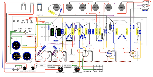
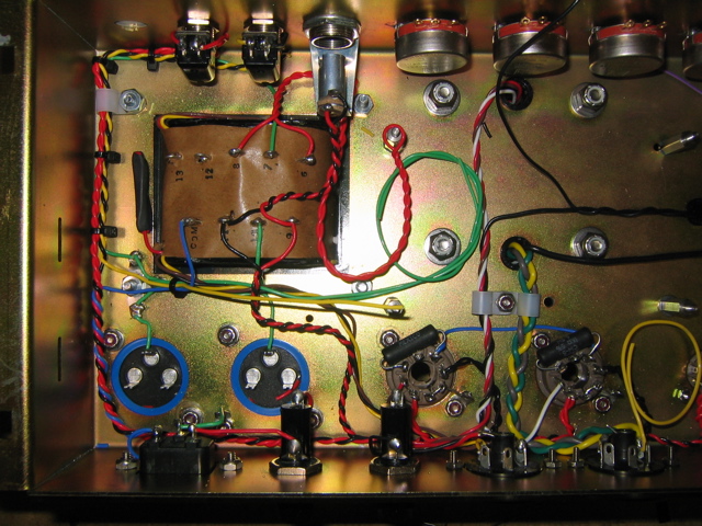
Yes use the black. Here is a layout of my JCM800 that may help you. Please note this is not the same as a 50 watt layout. The wires coming out of the PT are for using a voltage selector. Look at my voltage selector and you will see the corresponding wires to the PT. You can just individually heat shrink the unused wires. You can see in the second picture how I did not use the red and just bundled it and heat shrinked.
-
J.DavisNJ
- Senior Member
- Posts: 247
- Joined: Wed Dec 07, 2005 9:47 am
- Contact: