Parallel effects loop for Marshall style amps

Info for maintaining and tweaking your amp to perfection.

Moderator: VelvetGeorge

Post Reply
User avatar
novosibir
Senior Member
Posts: 4654
Joined: Tue Nov 22, 2005 2:32 pm
Just the numbers in order: 7
Location: Nuernberg, Germany
Contact:

Post by novosibir » Fri May 02, 2008 8:32 am

Capi wrote:I am working on a class A amplifier and I would like to install this loop. The amplifier has three gain stages, equalizer and master. Run at 310-320V in the preamp section. EL34, 6L6, KT66 at the power amp ...

I want to install the loop after the master. Do I have to modify some value of resistance to drive correctly the power amp?
Even Jesus couldn't say this - before looking at the schem of the amp 8)

Larry
The fault almost always is sitting in front of the amp :wink:

Larry's Website now with included Pix's Gallery

EddyInChicago
Senior Member
Posts: 212
Joined: Wed Jan 09, 2008 1:27 am

Post by EddyInChicago » Sat May 03, 2008 9:18 pm

Hi Larry,

Thank you for the loop schematic....much appreciated. I'm a student of Electronics Engineering, but, I'm very disappointed that no
college out there teached "tube theory" and design!! Maybe I'm fourty or so years too late... :roll: . Anyway, I have a few questions,
if I may ask of you?

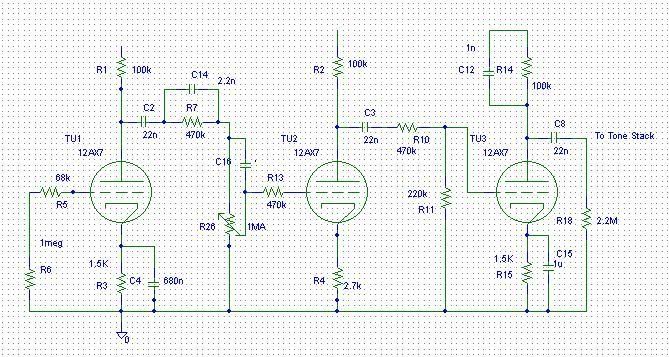
1) In past replies you spoke about the loops decibel characterists
"Now you could patch in a guitar cord from Send to
Return (instead of an effects device) and with the Send Level & Return Level dimed you'd get an additional boost of about +12dB.
To practice with this, set the Send
Level dimed and use the Return Level as a 'Post Gain Control"
and
"The dry path
of the loop has an attenuation of -33.0dB with the Return Level on zero or dimed and an attenuation of -32.5dB with the Return Level
on about 6...7, when nothing is plugged in.

The recovery stage has an amplification of +35.4dB, that means, that the signal with the loop will be slightly amplified by about +3dB - theoretical.

That's based on average tube datas, but when you have a pretty strong tube for the loop, then it might be a tad more, kinda +5dB...+6dB.

In this case you can fine tweak the attenuation by swapping the 68K with a 56K, a 47K or even a 39K for more attenuation, to
get to exactly that point, where it would be w/o the loop section"
I know you may not have time for a "tutorial" on circuit design
and analysis, but, any information is much appreciated.
My question is how are these measurements of this circuit calculated?

2) Can you help me with understanding the wiring for the input/output jacks? (I seem to be having a problem understanding
which are the ground, switch..etc lugs).

3) I believe, in one of your replies, you mentioned that this loop (when not used) does not color the amp except maybe +1 or +2 dB's. Is it a good idea to use a trim pot somewhere in the circuit to "tune" the circuit further to not have any dB boost when nothing is pluged in (0 dB's)? if so, where would you place that pot? (Note: on my work bench I do have a audio generator, DMM, O-Scope...etc. I'm thinking I would need to have some sort of an audio signal in the amp to see the input and output of this loop)

4) Any books I can purchase that you recoment that does a good job with tube theory and design?

5) I LOVE YOU LARRY !!!!!!! Will you adopt me ? :lol:

THANK YOU,

Ed

User avatar
novosibir
Senior Member
Posts: 4654
Joined: Tue Nov 22, 2005 2:32 pm
Just the numbers in order: 7
Location: Nuernberg, Germany
Contact:

Post by novosibir » Sat May 03, 2008 9:40 pm

1) Simple voltage divider calculation, but it's very complex, since one divider is part of the previous, aso. - so if you want to calculate it, start right in the schem and go further to the left step by step from junction to junction

2) The inner circle is the tip of the jack, the outer circle is ground, the arrow is the switching contact. Yes, I know, my symbols aren't standard :wink:

3) Use a 39K in series with a 25K trim pot instead of the 68K to ground, if you want to trim it exactly to 0dB. But in reality you haven't to care about +/- a few dB.

4) Kevin O'Connors TUT series, especially Vol. 3 & 5 and Dave Funk's Tube Amp Workbook

5) Shure! IIRC then you're my 27-th son :mrgreen:

Larry
The fault almost always is sitting in front of the amp :wink:

Larry's Website now with included Pix's Gallery

User avatar
wdelaney72
Senior Member
Posts: 1619
Joined: Sun Jan 22, 2006 9:04 pm
Location: Chicago Suburbs

Post by wdelaney72 » Sat May 03, 2008 9:50 pm

Larry's the best. I'm too old to be adopted. I'll just have to settle for sharing an Ayinger Jahrhundert should I ever save enough pennies to cross the pond. :lol:
Walter

"There's no great thing in being a soloist. I think the hardest thing is to play together with a lot of people, and do it right." - Angus Young, 1984

EddyInChicago
Senior Member
Posts: 212
Joined: Wed Jan 09, 2008 1:27 am

Post by EddyInChicago » Wed May 07, 2008 2:51 am

Hello Larry and All,

I came across this schematic of the rack mount (external) tube FX-loop Mr. Dumble built for a few clients. This is supposed to be accurate or as much as possible to the real thing. I just thought I may share it withh all of you and to get your comments on this circuit.

Larry......Have you ever come across this circuit on the internet? Do you think there may be a problem with this design just by your observation? (of course, the power supply is left out which is faily simple to design)

Has anyone built this loop?

Just curious :?

Take care all.......Ed
Attachments
DumbleLator.pdf
The "Rumblelator"
(10.58 KiB) Downloaded 233 times

User avatar
novosibir
Senior Member
Posts: 4654
Joined: Tue Nov 22, 2005 2:32 pm
Just the numbers in order: 7
Location: Nuernberg, Germany
Contact:

Post by novosibir » Wed May 07, 2008 5:12 am

EddyInChicago wrote:Larry......Have you ever come across this circuit on the internet? Do you think there may be a problem with this design just by your observation?
I'm familiar with the Dumbleator, later redrawn as the Rumbleator already more than 10 years now.

It's a serial loop (not a parallel), where the entire signal has to go through the cathode follower, who's colouring the sound and in the layout here extremely dynamics limiting.

This loop - since serial - forces the entire signal, to run through all the semiconductor devices in your effects and doesn't leave the dry signal 'untouched'!

The Send isn't lo sensitivity, since fed from the 250K pot AFTER the CF - and is only then lo sensitivity, when the Send is dimed!

And the Send & Return are acting like 2 additional Masters in the entire signal chain.

Who needs all this handicaps in a loop section?

Larry
The fault almost always is sitting in front of the amp :wink:

Larry's Website now with included Pix's Gallery

User avatar
johniss0001
Senior Member
Posts: 1404
Joined: Tue Mar 16, 2004 5:03 pm
Just the numbers in order: 7
Location: Hove England
Contact:

Post by johniss0001 » Wed May 07, 2008 7:29 am

i know this is a double post but can some1 please confirm this as this amp is not a marshall and has a slightly diff PI the PI is a 12AT7.

i am attempting to build the loop but i want to clear afew things up for starters this loop isn't going in a marshall so that is the confusing part.

ok sound citys have a weird way of doing things and looking at a 50 watt schematic there is a weird divider before the PI B+ so this is a tad confusing

scematic below of sound city
http://www.soundcitysite.com/sc_webpages/sc_50_plus.jpg

and is it safe to issume that pins 4,5 and 9 are grounded?
John Ross

Respect the FATHER OF LOUD Jim Marshall

Capi
Senior Member
Posts: 62
Joined: Sat Mar 29, 2008 2:43 am
Location: Spain

Post by Capi » Wed May 07, 2008 2:57 pm

novosibir wrote:
Capi wrote:I am working on a class A amplifier and I would like to install this loop. The amplifier has three gain stages, equalizer and master. Run at 310-320V in the preamp section. EL34, 6L6, KT66 at the power amp ...

I want to install the loop after the master. Do I have to modify some value of resistance to drive correctly the power amp?
Even Jesus couldn't say this - before looking at the schem of the amp 8)

Larry
Hi!

The preamp is similar to Soldano Atomic without the cathode follower. The EQ is plate driven. After the tone controls is the Master and the power stage. I use the Triode of cathode follower for the second stage of clean channel.

My intention is to use the loop after the master and I wonder whether we need to change some value

I have no outline drawn, sorry

User avatar
novosibir
Senior Member
Posts: 4654
Joined: Tue Nov 22, 2005 2:32 pm
Just the numbers in order: 7
Location: Nuernberg, Germany
Contact:

Post by novosibir » Wed May 07, 2008 4:34 pm

Capi wrote:My intention is to use the loop after the master and I wonder whether we need to change some value
I'd recommend to run the Treble into the loop section and put the Master on the plate of the recovery stage just after the loop section and before the PI input. This has the benefit, that you haven't always to readjust the effects levels, when you're changing the amp's loudness with the Master.

Larry
The fault almost always is sitting in front of the amp :wink:

Larry's Website now with included Pix's Gallery

Capi
Senior Member
Posts: 62
Joined: Sat Mar 29, 2008 2:43 am
Location: Spain

Post by Capi » Thu May 08, 2008 12:21 am

The power stage is class A ( single-ended ) and I haven't PI :wink:

C ya!

User avatar
novosibir
Senior Member
Posts: 4654
Joined: Tue Nov 22, 2005 2:32 pm
Just the numbers in order: 7
Location: Nuernberg, Germany
Contact:

Post by novosibir » Thu May 08, 2008 5:11 am

Capi wrote:The power stage is class A ( single-ended ) and I haven't PI :wink:
The next time when you're asking for some advice you should give all informations upfront, because some people (me too) don't like guesswork very much.

Larry
The fault almost always is sitting in front of the amp :wink:

Larry's Website now with included Pix's Gallery

Capi
Senior Member
Posts: 62
Joined: Sat Mar 29, 2008 2:43 am
Location: Spain

Post by Capi » Thu May 08, 2008 12:37 pm

Sorry, English is not my language and I do what I can. It is not easy to express things in a language that is not mine own. I said that the amplifier is a Class A, but did not specify the topology is single-ended.

Capi
Senior Member
Posts: 62
Joined: Sat Mar 29, 2008 2:43 am
Location: Spain

Post by Capi » Mon May 12, 2008 12:31 am

Well, I attach the schematic preamplifier. My first intention was to put the loop after the master. Recall that the amplifier is single-end with EL34 or 6L6 or KT66

Capi
Senior Member
Posts: 62
Joined: Sat Mar 29, 2008 2:43 am
Location: Spain

Post by Capi » Mon May 12, 2008 12:35 am

Image

:wink:

The Master is after EQ ( plate driven afeter 22n/2M2 ) like in marshall 2203

User avatar
Gee Donner
Senior Member
Posts: 94
Joined: Wed Dec 19, 2007 3:09 pm
Location: Sweden, Östergötland

Post by Gee Donner » Wed May 14, 2008 6:34 am

I was planning on doing the same kind of installation as Ricky Lee. Meaning extending the circuitboard and put Larrys FX on there. I need even more PTP board space for other mods in the beginning of the signal path (preamp). So I thinking maybe its possible to "slide" the complete board so it is "underneath" the PT (using a metro amp alu chassi with the filtercaps on the outside and stand up PT), without getting any disurbing noise from the PT. How far can I slide it. Check picture please! I did some paint changes on Ricky Lees Picture to describe what I mean. In the picture i "moved" the PTP board. Now, this pic is not with the stand up transformer.

I know Larry has his PTPs all the way back underneath his PT...hmmm

http://www.putfile.com/pic/8145972
///G
Are you a guitarist or a musician?
My MTS and plexi related images

Post Reply