Not familiar with these either, but the manuals I could find online show both of those also having reference level switches, so they should work fine with them set at the -10dBu setting I believe. Not sure if all units had these switches though, so check your particular manual/unit over.psychodave wrote:I just ordered 2 kits for my amps... but I didnt realize there may be issues with using rack effects. I primarily use a Rockton Intellifex and Replifex. Will the loop work with these effects?
FX loops coming to Metro.
Moderator: VelvetGeorge
-
SDM
- Senior Member
- Posts: 1644
- Joined: Sun Feb 26, 2006 6:24 am
- Just the numbers in order: 13492
- Location: MI
Re: FX loops coming to Metro.
-Steve
Layout site
Layout site
-
psychodave
- Senior Member
- Posts: 126
- Joined: Fri Dec 10, 2004 11:38 pm
Re: FX loops coming to Metro.
Cool. They all have the -10 db buttons. 
I have been wanting a loop badly. I have the Larry loop, but I have been afraid to actually sit down and do it. Now I can with this loop.
NOTE: Is it a "must" to use the switch? I hate to have to drill additional holes if it is not necessary. If I do end up using the switch, can I move if further away from the loop? It is a little too close for my liking (I would like it about an inch away from the jack).
Thanks... I am sure I will ask more questions along the way
-
SDM
- Senior Member
- Posts: 1644
- Joined: Sun Feb 26, 2006 6:24 am
- Just the numbers in order: 13492
- Location: MI
Re: FX loops coming to Metro.
You don't have to use the switch, just run the shielded wire coming from treble pot wiper to pad labeled "IN", use "OUT" pad for other shielded wire going to PI cap. Simple as that.
Can also move the switch, but the board bottom is also a shield, so best to keep it over the loop board area as strong signals run to/from the switch. Proven to work well where it's located on the template of course, but moved away from the board a bit vertically should pose no trouble, nor if kept reasonably near the general vicinity marked on the template.
Obviously I cannot verify that any random switch position will work without issues of course, but if you need/want to mount it much further away or in an unusual place, you can just shield the wires from loop board to switch and that should take care of/head off any potential problems.
-Steve
Layout site
Layout site
-
psychodave
- Senior Member
- Posts: 126
- Joined: Fri Dec 10, 2004 11:38 pm
Re: FX loops coming to Metro.
Thanks for the reply...
Okay, possibly the last question...
I would like to put the loop to the far left (looking at the back) of my amps. My SL was modded by Mark Cameron, and has all of the output jacks used up and my 2204 only has 2 outputs and doesnt have room... Would this pose any issues? Of course I would be using shielded wire where ever possible.
-
SDM
- Senior Member
- Posts: 1644
- Joined: Sun Feb 26, 2006 6:24 am
- Just the numbers in order: 13492
- Location: MI
Re: FX loops coming to Metro.
Very hard to answer that without knowing how it was modded. If it's a Jose type mod or HG Jose type mod, probably won't be a problem location wise, but you'll need to install it in the circuit like you would in a Super Lead. So it'd go after the master volume, hooked up between treble pot wiper and PI input - IF it has a Jose style master in there now with perhaps a PP switch to turn on/off the zeners.
If it still has a conventional 2203 style master following the tone stack, should be okay to mount it between treble pot and master as per instructions example.
These loops are set up expecting the signal level strength and impedances you'd have in a typical classic Marshall after the tone stack, so covers the kits Metro offers and also works great in a 2203 and many other amps, but not all circuits will be appropriate for it. Send/return levels could be off in the wrong application, impedances off causing some tonal change, so without knowing exactly what it would be interfacing to here, cannot guarantee it will work out perfectly.
Last edited by SDM on Wed Jan 14, 2009 3:41 am, edited 1 time in total.
-Steve
Layout site
Layout site
-
5150loveeddie

- Senior Member
- Posts: 3340
- Joined: Mon Apr 12, 2004 8:52 pm
- Just the numbers in order: 13492
- Location: Montreal, Quebec CANADA
Re: FX loops coming to Metro.
Steve, I just installed the loop in my 50w el34 type plexi, wow I can't beleive how well it works, so simple and not invasive, you did the best job dude, this is it for me!!
Folks that loop is the loop's loop!!! Period!!!
Hey sold my Scope finally!!
Folks that loop is the loop's loop!!! Period!!!
Hey sold my Scope finally!!
Glutathione increase specialist
http://www.max.com/science/448523/full/ ... lutathione" onclick="window.open(this.href);return false;
http://www.max.com/science/448523/full/ ... lutathione" onclick="window.open(this.href);return false;
-
xbearxau
Re: FX loops coming to Metro.
Steve, is it possible to buy this loop as a bare kit, un assembled?
The spacing for the jacks doesnt suit my intended application, so I was going to scrap the board and etch a new one with different spacing.
If this is possible please let me know.
Cheers,
Gary.
The spacing for the jacks doesnt suit my intended application, so I was going to scrap the board and etch a new one with different spacing.
If this is possible please let me know.
Cheers,
Gary.
-
psychodave
- Senior Member
- Posts: 126
- Joined: Fri Dec 10, 2004 11:38 pm
Re: FX loops coming to Metro.
[quote="SDM"]Very hard to answer that without knowing how it was modded. If it's a Jose type mod or HG Jose type mod, probably won't be a problem location wise, but you'll need to install it in the circuit like you would in a Super Lead. So it'd go after the master volume, hooked up between treble pot wiper and PI input - IF it has a Jose style master in there now with perhaps a PP switch to turn on/off the zeners.
If it still has a conventional 2203 style master following the tone stack, should be okay to mount it between treble pot and master as per instructions example.
These loops are set up expecting the signal level strength and impedances you'd have in a typical classic Marshall after the tone stack, so covers the kits Metro offers and also works great in a 2203 and many other amps, but not all circuits will be appropriate for it. Send/return levels could be off in the wrong application, impedances off causing some tonal change, so without knowing exactly what it would be interfacing to here, cannot guarantee it will work out perfectly.[/quote]
Thanks Steve.
I have both an Aldrich (100 watt) and a HG Jose (50 watt) like you describe above. I think you are correct with regards to the Jose having to be set up like a SL since it does switch (PP) zeners on/off. I am also trying to confirm with Mark before I proceed.
-
psychodave
- Senior Member
- Posts: 126
- Joined: Fri Dec 10, 2004 11:38 pm
Re: FX loops coming to Metro.
I installed the loop into a 1983 Marshall JCM 800 2204 last night. Took about 2 hours to do (since I was watching football at the same time). I installed the loop to the far left (when viewing from the back). I also put the on/off switch further out from the jacks.
There were a few issues with the install. The first was the jacks... the washer that come with the jacks was too small and when fully tightened, it was still loose. Fortunately, I have correct thicker washers to use. If not, the entire build would be at risk since it is not wise to have left it loose with 300 volts running to it. My next issue was the B+ wiring. Since I build it on a 50 watt amp, I just removed typical wire that takes place of a resistor on the board at the PI (100 watters use 2 10k resistors). The issue was trying to get a wire to actually fit in the B+ spot on the board. I have regular multi core wire (cant remember the thickness, but it was typical to the heater wire on the pre-amp tubes)) which was too thick to fit, so I ended up using solid core wire. I will probably change out to better wire later. I ran the B+ wire from the board, all along the back wall of the amp between the output jacks and the heater wires. Solid core wire stayed put, but I think I will put a few small blobs of silicone to hold better.
My suggestion is to add thicker washers to the kit and to include 1 or 2 feet of wire for longer B+ runs.
As for its sound. It sounds great, no change of tone with it on or off!!! I also use Rocktron Intellifex set up as normal. I didn’t have to use the -10db setting. Pedals also sounded and worked great.
Where can I get the 600V thin wire that is provided for the on/off switch? I would like to get a spool of it.
I will post a pic later.
-
budubum
- Senior Member
- Posts: 429
- Joined: Fri Jun 20, 2008 2:39 pm
Re: FX loops coming to Metro.
psychodave wrote:I installed the loop into a 1983 Marshall JCM 800 2204 last night. Took about 2 hours to do (since I was watching football at the same time). I installed the loop to the far left (when viewing from the back). I also put the on/off switch further out from the jacks.
There were a few issues with the install. The first was the jacks... the washer that come with the jacks was too small and when fully tightened, it was still loose. Fortunately, I have correct thicker washers to use. If not, the entire build would be at risk since it is not wise to have left it loose with 300 volts running to it. My next issue was the B+ wiring. Since I build it on a 50 watt amp, I just removed typical wire that takes place of a resistor on the board at the PI (100 watters use 2 10k resistors). The issue was trying to get a wire to actually fit in the B+ spot on the board. I have regular multi core wire (cant remember the thickness, but it was typical to the heater wire on the pre-amp tubes)) which was too thick to fit, so I ended up using solid core wire. I will probably change out to better wire later. I ran the B+ wire from the board, all along the back wall of the amp between the output jacks and the heater wires. Solid core wire stayed put, but I think I will put a few small blobs of silicone to hold better.
My suggestion is to add thicker washers to the kit and to include 1 or 2 feet of wire for longer B+ runs.
As for its sound. It sounds great, no change of tone with it on or off!!! I also use Rocktron Intellifex set up as normal. I didn’t have to use the -10db setting. Pedals also sounded and worked great.
Where can I get the 600V thin wire that is provided for the on/off switch? I would like to get a spool of it.
I will post a pic later.
your installation is very helpfull o me..
i still have a bit doubts about noise and possibel interference though.
see, ill be installing this in a 1987x chassis and iv already replaced one output jack for my resonace control.
i want that resonance control just there and not on the front panel bcoz the NFB is veryu senstive.
my doubt is that, if my calculations are correct, the loop board will be just below between the v1 and v2 socket if we are to center that board on the middle of the sockets.
SDM said that the board acts like a shield and that may be true but how about the B+ wire?that goes to the PI spot? i would have to draw a LONG wire to get there. B+ could what, interfeere with nearby signal wires of v2 and v3 plus dont forget the speaker jack (jack has everything going meaning trouble for any interfereing signals or hot b+ wires) plus the resonance control that bears the twisted shielded wires.
ill be attaching now a picture for you and also SDM might inspect before ill proceed with the ordering.
i know that im hijacking this thread but im very confuse.
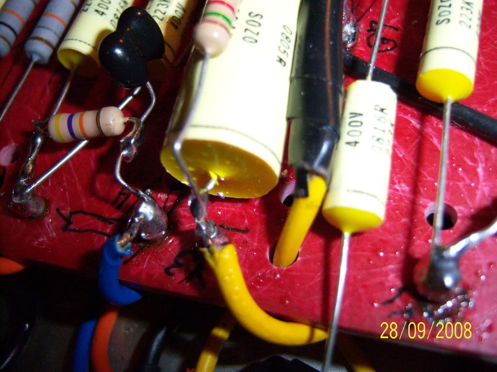
i changed the tone stack from 33k to 47k for that lower mid thuump, being lazy myself and didnt felt unsoldering the other leg of the 33k, i went and got me a scissors (didnt have tiny pliers for the tight job) i cut the otehr leg of the then one-leg-hangin 33k on the .68uf side and when i cut the 33k leg, i accidentally jerked the scissors and well as you see, "MIGHT" have damaged the .68uf.
if seeing from the attached picture, one side was out of the waxy body of the cap while the other is still intact, you think its still ok?
http://i303.photobucket.com/albums/nn12 ... 0_1876.jpg" onclick="window.open(this.href);return false;
http://i303.photobucket.com/albums/nn12 ... 0_1877.jpg" onclick="window.open(this.href);return false;
the amp is little to no noise otherwise.
thanks in advance,
kahelle
-
psychodave
- Senior Member
- Posts: 126
- Joined: Fri Dec 10, 2004 11:38 pm
Re: FX loops coming to Metro.
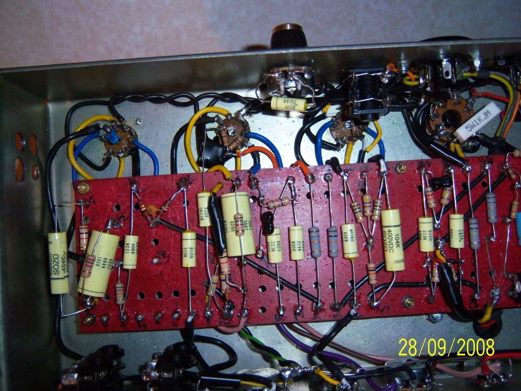
pic
http://i69.photobucket.com/albums/i59/p ... oop002.jpg" onclick="window.open(this.href);return false;
http://i69.photobucket.com/albums/i59/p ... oop002.jpg" onclick="window.open(this.href);return false;
-
budubum
- Senior Member
- Posts: 429
- Joined: Fri Jun 20, 2008 2:39 pm
Re: FX loops coming to Metro.
cool man cool.
yours definetely is out of reach for noise as its so away from the board.
still waiting for approval from SDM or from someone on for my case though:)
one thing. you said about the tone is untouched, does this also mean the gain is not altered of any sort aswell+
yours definetely is out of reach for noise as its so away from the board.
still waiting for approval from SDM or from someone on for my case though:)
one thing. you said about the tone is untouched, does this also mean the gain is not altered of any sort aswell+
-
psychodave
- Senior Member
- Posts: 126
- Joined: Fri Dec 10, 2004 11:38 pm
Re: FX loops coming to Metro.
I dont hear any difference in tone...when I used just a simple patch cord in the loop. Of course you will hear a difference in tone as you go through a pedal/effect since it is a series loop.
My B+ wire is almost a foot long. I need to get better wire and brace the resistor that is floating off the board. I was going to move the PI wire from the end of the board to the middle and then move the B+ wire to the PI's old spot...and place the resistor in place of the single bypass wire (for the additional 10k resister use in 100 watt amps). I could always just add the resistor to the loop board and run the wire to the board, but I thought it was better to have the resistor on the board side (maybe someone can comment). This way the board wouldnt look funky. I have no problems with noise with moving the switch further away as well.
Now I just need to get some good wire for the B+ run.
[quote="budubum"]cool man cool.
yours definetely is out of reach for noise as its so away from the board.
still waiting for approval from SDM or from someone on for my case though:)
one thing. you said about the tone is untouched, does this also mean the gain is not altered of any sort aswell+[/quote]
-
SDM
- Senior Member
- Posts: 1644
- Joined: Sun Feb 26, 2006 6:24 am
- Just the numbers in order: 13492
- Location: MI
Re: FX loops coming to Metro.
Glad to hear the loop works well for your application Psychodave. I used to add extra jack washers in the kits, but with the Metro kits and their thicker plastic panels, they weren't necessary. With an original thin metal panel different story, need the extra thickness, but these are aimed mainly for the kits. I'll talk to George about adding some extra washers though regardless.
As to the wire, the board holes fit the wire that comes with the kits. Usually guys have plenty of excess wire after building a kit, and again since they are mainly meant for the kits, figured guys would already have the excess wire they need. I'll talk to George about that too though, since it won't hurt to add those things for installs like yours.
On the B+ resistor you could kind of move it back, still soldered to that jumper, but so it sits over that jumper more and kinda look like its sitting where the other 10K would be if there was no jumper. Hope that made sense. Alternately, and to shorten the B+ run a bit, you could attach the loop resistor to the 10K leg circled in pic below. Then run resistor over the 10K's there or kinda past them a bit, whichever is easiest/most secure to you. Same B+ node there, just tapping that node at a closer spot to the board location.
Of course it something is working well may just want to leave alone.
- Attachments
-
- loop003.JPG
- (70.79 KiB) Downloaded 1459 times
-Steve
Layout site
Layout site
-
SDM
- Senior Member
- Posts: 1644
- Joined: Sun Feb 26, 2006 6:24 am
- Just the numbers in order: 13492
- Location: MI
Re: FX loops coming to Metro.
To Budubum,
Since you've got a PCB replacement board in a RI, take a look at the pic below, let me know the space you have there from board to chassis, and resonance pot to chassis. Some ideas on how it'd could hook up, it'll be tight, but has worked out fine in similar RoccO'cconor modded amps. You may want/need to also rotate the resonance control so the pot's lugs/cap are pointing away from the loop board, but that may not be needed.
Since you've got a PCB replacement board in a RI, take a look at the pic below, let me know the space you have there from board to chassis, and resonance pot to chassis. Some ideas on how it'd could hook up, it'll be tight, but has worked out fine in similar RoccO'cconor modded amps. You may want/need to also rotate the resonance control so the pot's lugs/cap are pointing away from the loop board, but that may not be needed.
- Attachments
-
- c.JPG
- (127.18 KiB) Downloaded 1446 times
-Steve
Layout site
Layout site