JTM 45/100 - Build story
Moderator: VelvetGeorge
-
neikeel

- Senior Member
- Posts: 7231
- Joined: Tue Dec 06, 2005 8:31 am
- Location: Suffolk, England
-
Xplorer

- Senior Member
- Posts: 2480
- Joined: Sun Apr 19, 2009 5:27 pm
- Just the numbers in order: 7
Re: JTM 45/100 - Build story
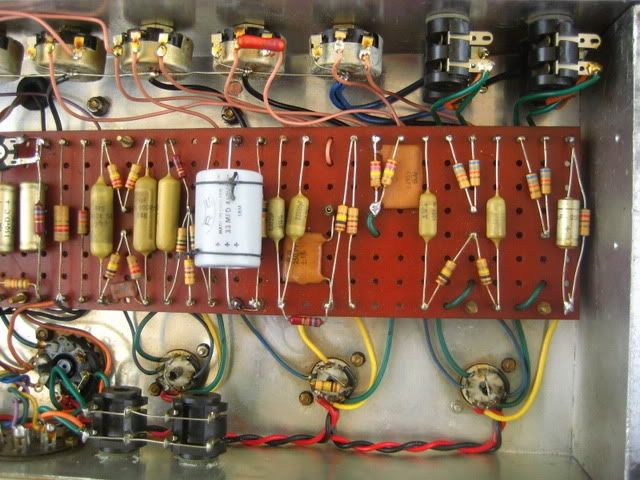
Taking my time. Now it's gonna be a tricky part with all the wires, under and over the board ...
if i remember correctly, some on V1 ( green and blue wires x 2 ) should be away from each other as much as possible, to avoid noises.
if i remember correctly, some on V1 ( green and blue wires x 2 ) should be away from each other as much as possible, to avoid noises.
- Attachments
-
- 48l.jpg
- (456.73 KiB) Downloaded 1449 times
-
BoogieEngineer
- Senior Member
- Posts: 227
- Joined: Sat Jun 30, 2012 1:53 am
- Just the numbers in order: 13492
- Location: La Jolla, CA
Re: JTM 45/100 - Build story
Looks great! Ten times better than my build 
-
neikeel
- Senior Member
- Posts: 7231
- Joined: Tue Dec 06, 2005 8:31 am
- Location: Suffolk, England
Re: JTM 45/100 - Build story
Yes.Xplorer wrote:Taking my time. Now it's gonna be a tricky part with all the wires, under and over the board ...
if i remember correctly, some on V1 ( green and blue wires x 2 ) should be away from each other as much as possible, to avoid noises.
You loop the green grid wires (from both the 68k pairs and 270k) up through the board (look on amp archives etc) allow the wires to stay in the air to the socket.
The blue plate wires go straight down from the turret to the chassis floor and along the chassis to the socket.
The yellow cathode wires not so crucial but make sure they cross the heaters at 90 degrees.
http://i76.photobucket.com/albums/j2/ne ... G_1718.jpg
Neil
-
VintageCharlie

- Senior Member
- Posts: 692
- Joined: Tue Sep 29, 2009 12:05 am
- Just the numbers in order: 7
Re: JTM 45/100 - Build story
Adrien, the populated board looks really great! Nice job! It's really a great feeling when this all comes together and the result really even nails the looks of originals. Can't wait the finished amp and some clips! 
-
Xplorer
- Senior Member
- Posts: 2480
- Joined: Sun Apr 19, 2009 5:27 pm
- Just the numbers in order: 7
Re: JTM 45/100 - Build story
Thanks for the nice compliments and advices ! 

Karlis, your amp isn't bad too
Today's progress shots : i started to solder the ground wires from the pots to the board, plus a few others. Then i took care of the pink wires and .... No more solder tin left ! i have to buy some when i can.
Karlis, your amp isn't bad too
Today's progress shots : i started to solder the ground wires from the pots to the board, plus a few others. Then i took care of the pink wires and .... No more solder tin left ! i have to buy some when i can.
-
axeman

- Senior Member
- Posts: 2465
- Joined: Wed Apr 02, 2008 1:21 pm
- Just the numbers in order: 7
- Location: Los Angeles
- Contact:
Re: JTM 45/100 - Build story
Nice, whats the part number of those top hat diodes?
-
Xplorer
- Senior Member
- Posts: 2480
- Joined: Sun Apr 19, 2009 5:27 pm
- Just the numbers in order: 7
Re: JTM 45/100 - Build story
They are BY114.
Guys, i have a stupid question. i have some 250v 1A fuse, as well as some 250v 4A. Gutpile talked about some 3A fuse for the mains fuse. is it ok with what i've got ?
Also : the mains fuse is the fuse on the pannel side, just near the bulgin plug, and the HT fuse is the fuse mounted inside the chassis near the transformer, right ?
Also, i'll ground the power board on a screw of the power transformer, i hope it'll be ok , and that it won't catch the vibrations and work of the power transformer ..
-
Xplorer
- Senior Member
- Posts: 2480
- Joined: Sun Apr 19, 2009 5:27 pm
- Just the numbers in order: 7
Re: JTM 45/100 - Build story
Today's progress shots, Now i just have to wire the AC cable with the plug, and reform the caps !!!
the BY114 i have ... well i have no specs on it, i guess i'll have to be lucky there. They're not mullard, they're miniwatt dario, more recent.
about the tube wires, i hope i'm right. i should not hurry, and check everything with the layout.
Tomorrow : caps reforming. From what i understand, i should :
- remove all the tubes
- Follow the wire that comes from the rectifier and runs to the standby switch. This is B+. At the other side of the standby switch, unsolder the wire (which should run to the mains filter caps). solder a 100k 2w resistor at this point of the switch with the other side soldered to the wire mentioned.
- let the fuses in
- unplug the amp from the speaker cab
- the amp set on wathever impedance.
- set my voltmeter on DC ( about 600 volts )
- measure every one or two hours the voltage with aligator clips of a voltmeter ( turned on and off when used to measure while the reforming process is active ) , placed on each side of the 100k 2w.
- wait the voltage to drop under 2-5 volts.
- then drain the caps with one aligator clip on the chassis, and the other ( still from the same cable ) connected to pin 1 of V1.
- reconnect the red wire to the standbye switch
- plug the amp and adjust the bias by ears and voltage reading
- compare the voltage at different points, with a voltage grid somewhere , i'll look for it.
- see if there are some strange values
- plug and play !!!
Advices welcome ! feel free to correct me ! this is dangerous stuff and high voltage.
-
Xplorer
- Senior Member
- Posts: 2480
- Joined: Sun Apr 19, 2009 5:27 pm
- Just the numbers in order: 7
Re: JTM 45/100 - Build story
i just switched the amp on, to reform the caps. But my voltmeter can't read values over 600 volts. I wonder if there's a problem, cause after 10-15 minutes it still can't read any AC volt value across the 100k resistor.
i thought that it had to go up to 600 volts then lowering down to about 50 volts, then down and down, to the desired value under 3-5 volts.
when i switch to the standbye mode, the volt meter starts to say 1700volts, 1400 .. 1300, then 450, 300 , 220 ... 50 , 20 , 10 ....
is there another way to verify that the amp circuit is set properly, other than measuring the tube pins even without tubes in the amp ?
Thanks !
-
Xplorer
- Senior Member
- Posts: 2480
- Joined: Sun Apr 19, 2009 5:27 pm
- Just the numbers in order: 7
Re: JTM 45/100 - Build story
okay .... Now the volt meter is dead ! i did BS with it and burned the fuses of the amp while trying to see what it would give by hooking both 560v taps to the aligator clips of the meter. pff 
i'll buy another cheap volt meter to test the amp prioor to the fluke that a friend is offering to me soon.
But mystery,everything looks fine on the amp.
rectifier diodes perhaps ? i don't know their specs.
a forgotten connection ??
the red lamp lights itself, the transformer does a quiet transformer sound, fuses are replaced now ...
my volt meter maybe needs to hook itself to some other points, to check the amp, i dunno which.
Did this experience happend to you ?
-
neikeel
- Senior Member
- Posts: 7231
- Joined: Tue Dec 06, 2005 8:31 am
- Location: Suffolk, England
Re: JTM 45/100 - Build story
It is DC not ac.Xplorer wrote:i just switched the amp on, to reform the caps. But my voltmeter can't read values over 600 volts. I wonder if there's a problem, cause after 10-15 minutes it still can't read any AC volt value across the 100k resistor.
i thought that it had to go up to 600 volts then lowering down to about 50 volts, then down and down, to the desired value under 3-5 volts.
when i switch to the standbye mode, the volt meter starts to say 1700volts, 1400 .. 1300, then 450, 300 , 220 ... 50 , 20 , 10 ....
is there another way to verify that the amp circuit is set properly, other than measuring the tube pins even without tubes in the amp ?
Thanks !
Tubes out, no load.
Go through the B+ line with a meter for continuity.
Neil
-
Xplorer
- Senior Member
- Posts: 2480
- Joined: Sun Apr 19, 2009 5:27 pm
- Just the numbers in order: 7
Re: JTM 45/100 - Build story
Thanks !
i tried before, ( when the volt meter was still alive ? maybe maybe not ) with the DC line but it did the same thing..
With B+ do you mean that i should connect one side of the volt meter ( Set on DC ) to the chassis, and another one on the rectifier diodes where a red wire goes to the standbye switch ? ( the other wire from the standbye switch going to the mains filter caps )
-
shakti
- Senior Member
- Posts: 2053
- Joined: Tue Apr 05, 2005 9:06 am
- Just the numbers in order: 7
- Location: Ramnes, Norway
Re: JTM 45/100 - Build story
That would be B+, yes. Remember, everything coming out of the power transformer is AC and must be measured accordingly if you measure directly between ground (chassis) and a transformer lug. After the rectifier you have DC.
I would make sure the connections on the PT are all correct - the lugs aren't individually labeled, so it's easy to get them switched around. Do you have a connection from the PT CT to ground? I can't see it clearly.
I'm also a little concerned about the look of many of your solder joints...too much solder IMO. It may not be the cause of your problems, but I would check continuity over every solder joint.
JTM45 RS OT, 1973 18W, JTM45/100, JTM50, JMP50 1986, JMP100 "West Coast", AC15, AC30, BF Super Reverb, Boogie Mk 1, Hiwatt CP103, DR103